Suzuki Grand Vitara JB416 / JB420. Manual — part 111
1D-112 Engine Mechanical: For J20 Engine
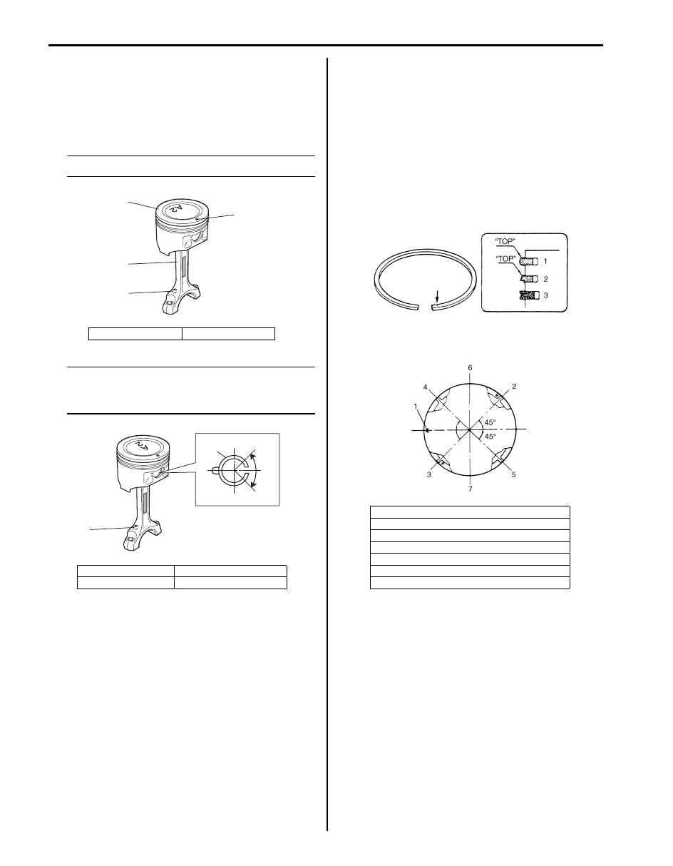
4) Install piston pin to piston (1) and connecting rod (3):
After applying engine oil to piston pin and piston pin
holes in piston and connecting rod, fit connecting rod
to piston as shown in figure and insert piston pin to
piston and connecting rod, and install piston pin
circlips.
NOTE
Oil hole (4) come on intake side.
NOTE
Circlip (4) should be installed so that circlip
end gap comes within such range as
indicated by arrow.
5) Install piston rings to piston:
• As indicated in figure at the left, 1st and 2nd rings
have “TOP” mark respectively. When installing
these piston rings to piston, direct marked side of
each ring toward top of piston.
• 1st ring (1) differs from 2nd ring (2) in thickness,
shape and color of surface contacting cylinder
wall.
Distinguish 1st ring from 2nd ring by referring to
figure.
• When installing oil ring (3), install spacer first and
then two rails.
6) After installing three rings (1st, 2nd and oil rings),
distribute their end gaps as shown in figure.
2. Front mark
4. Oil hole
1. Piston
3. Connecting rod
2. Front mark
5. Oil hole
1
2
3
4
I5JB0A142051-01
4
5
I4RH01140039-01
1. Front mark
2. 1st ring end gap
3. 2nd ring end gap and oil ring spacer gap
4. Oil ring upper rail gap
5. Oil ring lower rail gap
6. Intake side
7. Exhaust side
I5JB0A142052-02
I5JB0A142053-01
Engine Mechanical: For J20 Engine 1D-113
Pistons, Piston Rings, Connecting Rods and
Cylinders Inspection and Cleaning
S5JB0A1426039
Inspection
Cylinder
• Inspect cylinder walls for scratches, roughness, or
ridges which indicate excessive wear. If cylinder bore
is very rough or deeply scratched, or ridged, rebore
cylinder and use over size piston.
• Using a cylinder gauge, measure cylinder bore in
thrust and axial directions at two positions as shown in
figure.
If any of following conditions is noted, rebore cylinder.
1) Cylinder bore diameter exceeds limit.
2) Difference of measurements at two positions
exceeds taper limit.
3) Difference between thrust and axial measurements
exceeds out-of-round limit.
Cylinder bore diameter
Standard: 84.000 – 84.020 mm (3.3070 – 3.3078
in.)
Limit: 84.050 mm (3.3090 in.)
Taper and out-of-round
Limit: 0.10 mm (0.004 in.)
NOTE
If any one of four cylinders has to be rebored,
rebore all four to the same next oversize.
This is necessary for the sake of uniformity
and balance.
Pistons
• Inspect piston for faults, cracks or other damages.
Damaged or faulty piston should be replaced.
• Piston diameter:
As indicated in figure, piston diameter should be
measured at a position 26.5 mm (1.04 in.) (“a”) from
piston skirt end in the direction perpendicular to piston
pin.
Piston diameter
• Piston clearance:
Measure cylinder bore diameter and piston diameter
to find their difference which is piston clearance.
Piston clearance should be within specification as
follows. If it is out of specification, rebore cylinder and
use oversize piston.
Piston clearance
0.02 – 0.04 mm (0.0008 – 0.0015 in.)
NOTE
Cylinder bore diameters used here are
measured in thrust direction at two positions.
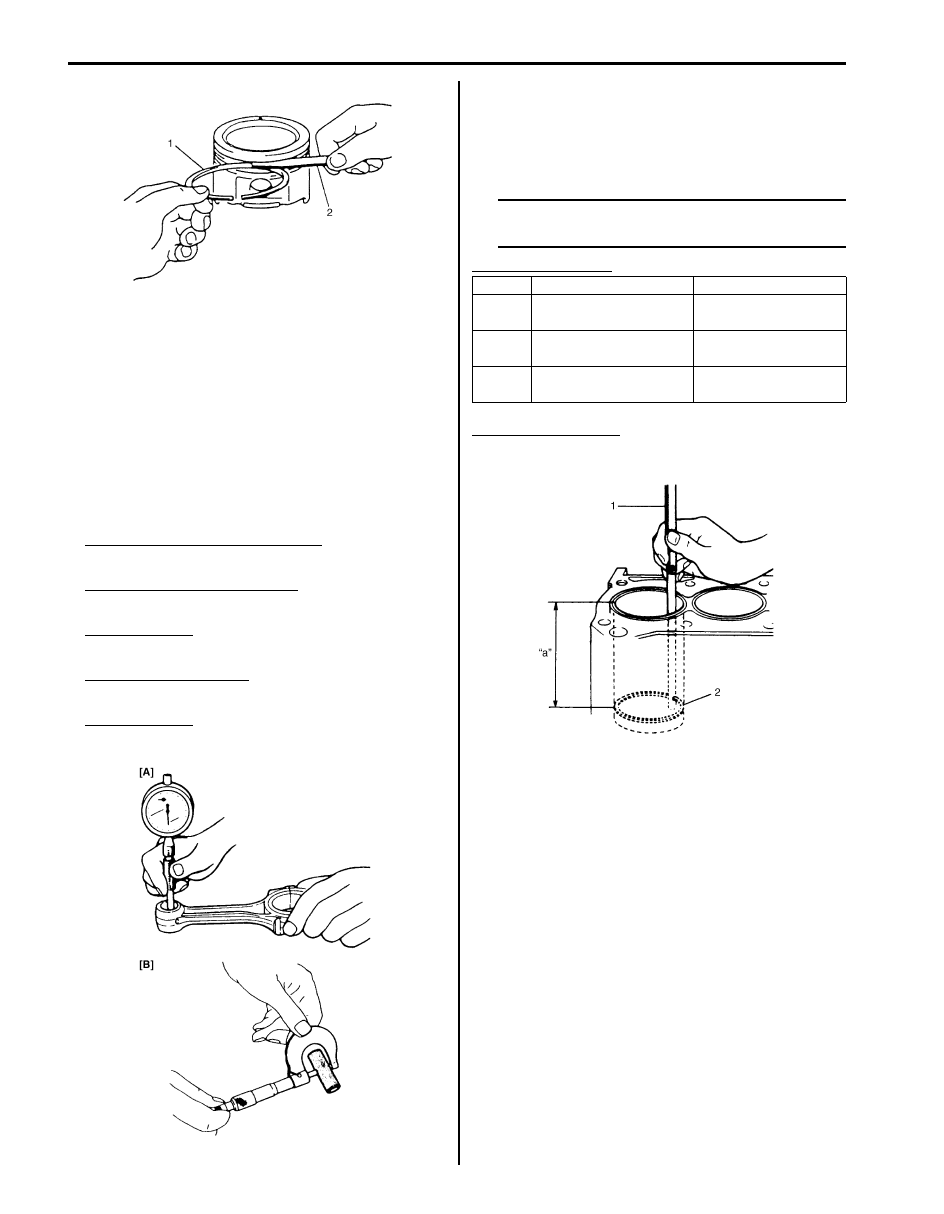
• Ring groove clearance:
Before checking, piston grooves must be clean, dry
and free of carbon.
Fit new piston ring (1) into piston groove, and
measure clearance between ring and ring land by
using thickness gauge (2).
If clearance is out of specification, replace piston.
Ring groove clearance
1. 50 mm (1.96 in.)
2. 95 mm (3.74 in.)
I5JB0A142046-01
Standard
83.9700 – 83.9900 mm
(3.3059 – 3.3067 in.)
Oversize: 0.50 mm
(0.0196 in.)
84.4700 – 84.4900 mm
(3.3256 – 3.3264 in.)
Item
Standard
Limit
Top
ring
0.03 – 0.07 mm
(0.0120 – 0.0027 in.)
0.12 mm (0.0047 in.)
2nd
ring
0.02 – 0.06 mm
(0.0008 – 0.0023 in.)
0.1 mm (0.0039 in.)
Oil ring
0.06 – 0.15 mm
(0.0024 – 0.0059 in.)
—
I2RH01140157-01
1D-114 Engine Mechanical: For J20 Engine
Piston pin
• Check piston pin, connecting rod small end bore and
piston bore for wear or damage, paying particular
attention to condition of small end bore bush. If pin,
connecting rod small end bore or piston bore is badly
worn or damaged, replace pin, connecting rod or
piston.
• Piston pin clearance: Check piston pin clearance in
small end.
Replace connecting rod if its small end is badly worn
or damaged or if measured clearance exceeds limit.
Piston pin clearance in small end
Standard: 0.003 – 0.014 mm (0.0001 – 0.0005 in.)
Piston pin clearance in piston
Standard: 0.006 – 0.017 mm (0.00024 – 0.00067 in.)
Small-end bore
21.003 – 21.011 mm (0.8269 – 0.8272 in.)
Piston pin diameter [B]
20.997 – 21.000 mm (0.8267 – 0.8268 in.)
Piston bore [A]
21.006 – 21.014 mm (0.8270 – 0.8273 in.)
Piston rings
To measure end gap, insert piston ring (2) into cylinder
bore and then measure the gap by using thickness
gauge (1).
If measured gap is out of specification, replace ring.
NOTE
Clean carbon and any other dirt from top of
cylinder bore before inserting piston ring.
Piston ring end gap
Piston rings end gap
“a”: 120 mm (4.72 in.)
I2RH01140159-01
I5JB0A142054-02
Item
Standard
Limit
Top
ring
0.20 – 0.33 mm
(0.0079 – 0.0129 in.)
0.7 mm (0.0276 in.)
2nd
ring
0.33 – 0.48 mm
(0.0129 – 0.0188 in.)
0.7 mm (0.0276 in.)
Oil ring
0.20 – 0.50 mm
(0.0079 – 0.0196 in.)
1.8 mm (0.0709 in.)
I2RH01140161-01
Engine Mechanical: For J20 Engine 1D-115
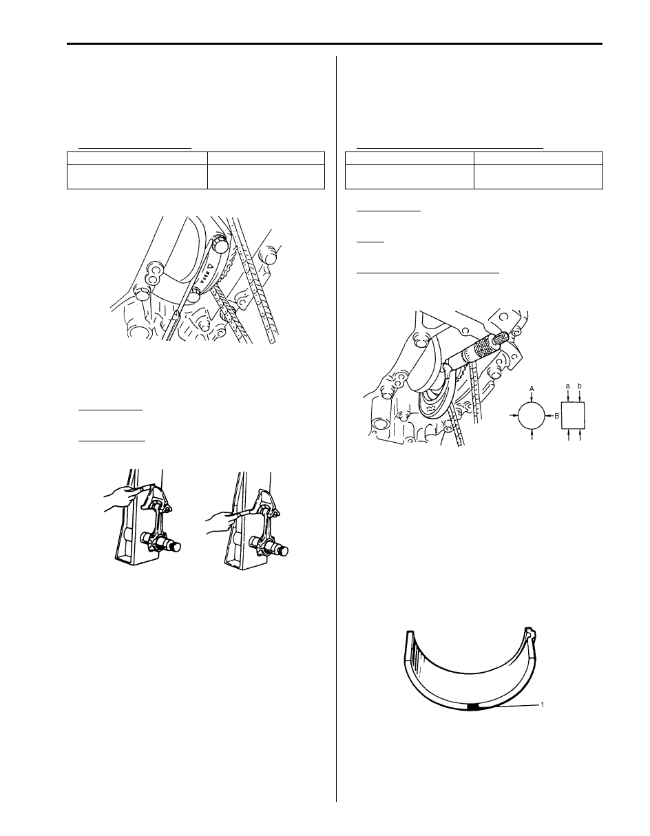
Connecting rod
• Big-end side clearance:
Check big-end of connecting rod for side clearance,
with rod fitted and connected to its crank pin in the
normal manner. If measured clearance is found to
exceed its limit, replace connecting rod.
Big-end side clearance
• Connecting rod alignment:
Mount connecting rod on aligner to check it for bow
and twist. If limit is exceeded, replace it.
Limit on bow
0.05 mm (0.0020 in.)
Limit on twist
0.10 mm (0.0039 in.)
Crank pin and connecting rod bearings
• Inspect crank pin for uneven wear or damage.
Measure crank pin for out-of-round or taper with a
micrometer. If crank pin is damaged, or out-of round
or taper is out of limit, replace crankshaft or regrind
crank pin referring to the following step 6).
Connecting rod bearing and crank pin
Out-of-round
“A” – “B”
Taper
“a” – “b”
Out-of-round and taper limits
0.01 mm (0.0004 in.)
• Connecting rod bearing general information:
Inspect bearing shells for signs of fusion, pitting, burn
or flaking and observe contact pattern. Bearing shells
found in defective condition must be replaced.
Two kinds of connecting rod bearings are available;
standard size bearing and 0.25 mm (0.0098 in.)
undersize bearing. For identification of undersize
bearing, it is painted red (1) at the position as
indicated in the figure, undersize bearing thickness is
1.605 – 1.615 mm (0.0632 – 0.0635 in.) at the center
of it.
Standard
Limit
0.25 – 0.40 mm
(0.0099 – 0.0150 in.)
0.45 mm (0.0177 in.)
I4RH01140041-01
I4RH01140053-01
Item
Standard
Crank pin diameter
49.982 – 50.000 mm
(1.9768 – 1.9685 in.)
I2RH01140163-01
I2RH01140164-01
Нет комментариевНе стесняйтесь поделиться с нами вашим ценным мнением.
Текст