Suzuki Grand Vitara JB416 / JB420. Manual — part 112
1D-116 Engine Mechanical: For J20 Engine
• Connecting rod bearing clearance:
a. Before checking bearing clearance, clean bearing
and crank pin.
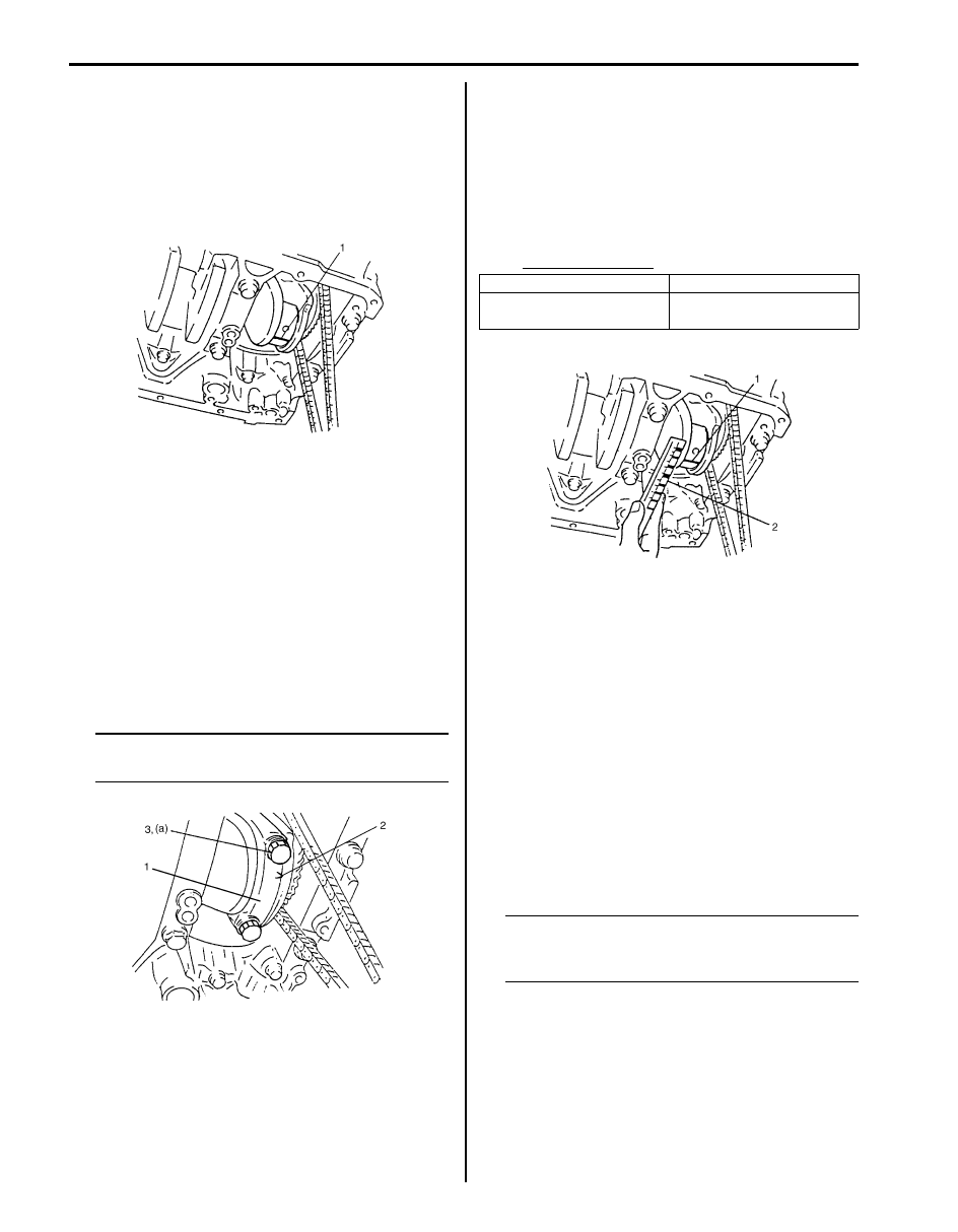
b. Install bearing in connecting rod and bearing cap.
c. Place a piece of gauging plastic (1) to full width of
crank pin as contacted by bearing (parallel to
crankshaft), avoiding oil hole.
d. Install connecting rod bearing cap (1) as follows.
i.
Point arrow mark (2) on cap to crankshaft
pulley side.
ii. Apply engine oil to connecting rod bolts (3).
iii. Tighten all connecting rod bolts to 15 N
⋅m (1.5
kgf-m, 11.0 lb-ft).
iv. Retighten them by turning through 45
°.
v. Repeat step d) once again.
Tightening torque
Connecting rod bolt (a): Tighten 15 N
⋅m
(1.5 kgf-m, 11.0 lb-ft), 45
° and 45° by the
specified procedure.
NOTE
Do not turn crankshaft with gauging plastic
installed.
e. Remove connecting rod bearing cap, and using a
scale (2) on gauging plastic envelope, measure
gauging plastic (1) width at the widest point
(clearance).
If clearance exceeds its limit, select connecting
rod bearing referring to “Pistons, Piston Rings,
Connecting Rods and Cylinders Inspection and
Cleaning: For J20 Engine” below mentioned item.
After selecting new bearing, recheck clearance.
Bearing clearance
f.
If clearance can not be brought to within its limit
even by using a new standard size bearing,
replace crankshaft or regrind crankpin to
undersize as follows.
– Install 0.25 mm undersize bearing to
connecting rod big end.
– Measure bore diameter of connecting rod big
end.
– Regrind crankpin to the following finished
diameter.
– Confirm that bearing clearance is within the
standard value.
NOTE
After checking the connecting rod bearing
clearance, make sure that checking for
“Connecting rod bolt deformation”.
I2RH01140165-01
I4RH01140037-01
Standard
Limit
0.045 – 0.063 mm
(0.0018 – 0.0025 in.)
0.08 mm (0.0031 in.)
Finished
crankpin
diameter
=
Measured big end bore
diameter (including
undersize bearing)
–
0.054 mm
(0.0021 in.)
I2RH01140167-01
Engine Mechanical: For J20 Engine 1D-117
• Selection of connecting rod bearings:
NOTE
• If bearing is in malcondition or bearing
clearance is out of specification, select a
new standard bearing according to the
following procedure and install it.
• When replacing crankshaft or connecting
rod and its bearing due to any reason,
select new standard bearings to be
installed referring to numbers stamped on
connecting rod and its cap and/or
alphabets stamped on crank web of No. 3
cylinder.
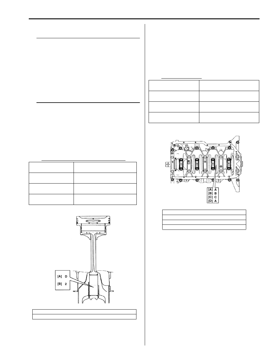
a. Check stamped numbers on connecting rod and
its cap as shown.
Three kinds of numbers (“1”, “2” and “3”)
represent the following connecting rod big end
inside diameters.
For example, stamped number “1” indicates that
corresponding connecting rod big-end inside
diameter is 53.0000 – 53.0060 mm (2.0867 –
2.0868 in.).
Connecting rod big-end inside diameter
b. Next, check crank pin diameter. On crank web of
No. 3 cylinder, four alphabets are stamped as
shown in the figure.
Three kinds of alphabet (“A”, “B” and “C”)
represent the following crank pin diameter
respectively.
For example, stamped “A” indicates that
corresponding crank pin diameter is 49.9940 –
50.0000 mm (1.9683 – 1.9685 in.).
Crank pin diameter
Stamped numbers
Connecting rod big-end
inside diameter
1
53.0000 – 53.0060 mm
(2.0867 – 2.0868 in.)
2
53.0061 – 53.0120 mm
(2.0869 – 2.0870 in.)
3
53.0121 – 53.0180 mm
(2.0871 – 2.0873 in.)
[A]: Weight indication mark (It is not necessary in servicing)
[B]: Connecting rod big-end inside diameter number
I2RH01140210-01
Stamped alphabet
Crank pin diameter
(without bearing)
A
49.9940 – 50.0000 mm
(1.9683 – 1.9685 in.)
B
49.9880 – 49.9939 mm
(1.9681 – 1.9682 in.)
C
49.9820 – 49.9879 mm
(1.9677 – 1.9680 in.)
[A]: Crankshaft pin diameter for No.1 cylinder
[B]: Crankshaft pin diameter for No.2 cylinder
[C]: Crankshaft pin diameter for No.3 cylinder
[D]: Crankshaft pin diameter for No.4 cylinder
I5JB0A142055-01
1D-118 Engine Mechanical: For J20 Engine
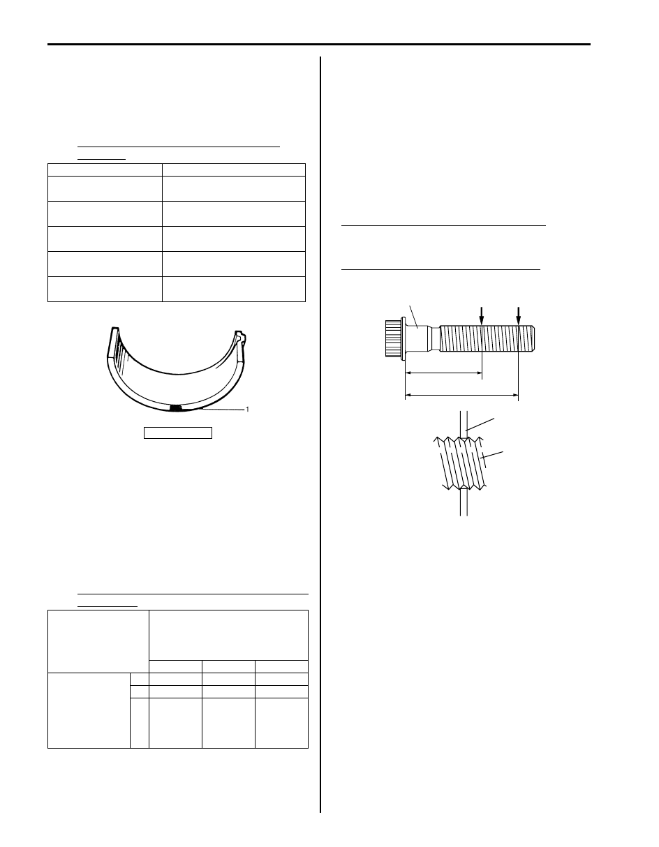
c. There are 5 kinds of standard bearings differing in
thickness. To distinguish them, they are painted in
the following colors at the position as indicated in
the figure.
Each color indicated the following thickness at the
center of bearing.
Standard size of connecting rod bearing
thickness
d. From number stamped on connecting rod and its
cap and alphabet stamped on crank web No. 3
cylinder, determine new standard bearing to be
installed to connecting rod big-end inside, by
referring to the table.
For example, if number stamped on connecting
rod and its cap is “1” and alphabet stamped on
crank web No. 3 cylinder is “B”, install a new
standard bearing painted in “Black” to its
connecting rod big-end inside.
Specifications of new standard connecting rod
bearing size
e. Check bearing clearance with newly selected
standard bearing referring to “Crank pin and
connecting rod bearings: For J20 Engine”.
If clearance still exceeds its limit, use next thicker
bearing and recheck clearance.
• Connecting rod bolt
Measure each thread diameter of connecting rod bolts
(1) at “A” on 28.5 mm (1.12 in.) from bolt mounting
surface and “B” on 42.0 mm (1.65 in.) from bolt
mounting surface by using a micrometer (2).
Calculate difference in diameters (“A” – “B”). If it
exceeds limit, replace connecting rod.
Connecting rod bolt measurement points
“a”: 28.5 mm (1.12 in.)
“b”: 42.0 mm (1.65 in.)
Connecting rod bolt diameter difference
limit (“A” – “B”): 0.1 mm (0.004 in.)
Cleaning
Clean carbon from piston head and ring grooves, using a
suitable tool.
Color painted
Bearing thickness
Green
1.482 – 1.485 mm
(0.05835 – 0.05846 in.)
Black
1.485 – 1.488 mm
(0.05847 – 0.05858 in.)
Colorless
1.488 – 1.491 mm
(0.05859 – 0.05870 in.)
Yellow
1.491 – 1.494 mm
(0.05871 – 0.05881 in.)
Blue
1.494 – 1.497 mm
(0.05882 – 0.05893 in.)
1. Paint
Number stamped on
connecting rod and its cap
(Connecting rod big end inside
diameter)
1
2
3
Alphabet
stamped on
crank web of
No. 3 cylinder
(Crank pin
diameter)
A
Green
Black
Colorless
B
Black
Colorless
Yellow
C Colorless
Yellow
Blue
IYSQ01141169-01
1
2
1
‘‘a’’
‘‘b’’
‘‘A’’
‘‘B’’
I4RH01140043-01
Engine Mechanical: For J20 Engine 1D-119
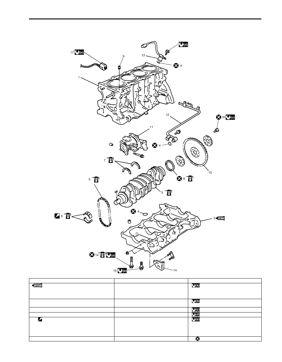
Main Bearings, Crankshaft and Cylinder Block Components
S5JB0A1426040
I5JB0A142056-02
1. Cylinder block
9. Check valve
17. Knock sensor
2. Lower crankcase
: Apply sealant 99000-31250 to mating
surface.
10. Flywheel
: Tighten 40 N
⋅m (4.0 kgf-m, 29.0 lb-ft), 0
N
⋅m (0 kgf-m, 0 lb-ft), 40 N⋅m (4.0 kgf-m,
29.0 lb-ft) and 58 N
⋅m (5.8 kgf-m, 42.0
lb-ft) by the specified procedure.
3. Crankshaft
11. Water pump
: Tighten 26 N
⋅m (2.6 kgf-m, 19.0 lb-ft) by
the specified procedure.
4. O-ring
12. Heater outlet pipe
: 70 N
⋅m (7.0 kgf-m, 51.0 lb-ft)
5. Oil pump chain
13. CKP sensor
: 11 N
⋅m (1.1 kgf-m, 8.0 lb-ft)
6. Main bearing
: Do not apply engine oil between cylinder
block and bearing, between lower crankcase
and bearing. Upper half of bearing has an oil
groove.
14. Crankcase bolt (10 mm thread diameter)
: 23 N
⋅m (2.3 kgf-m, 17.0 lb-ft)
7. Thrust bearing
15. Crankcase bolt (8 mm thread diameter)
: Do not reuse.
Нет комментариевНе стесняйтесь поделиться с нами вашим ценным мнением.
Текст