Suzuki Grand Vitara JB416 / JB420. Manual — part 279
7B-7 Air Conditioning System:
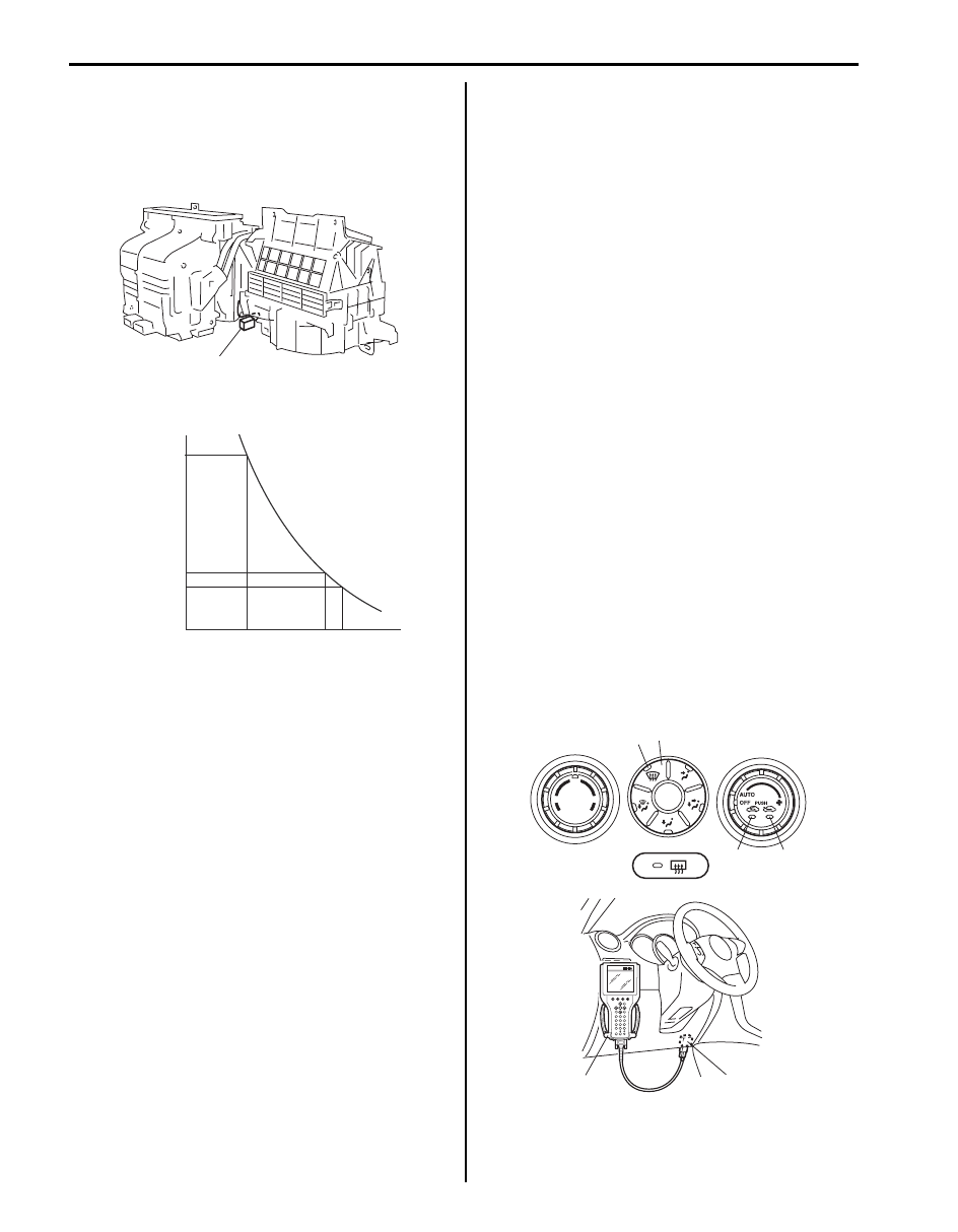
A/C Evaporator Temperature Sensor
Description
S5JB0A7201002
The A/C evaporator temperature sensor (1) is a
temperature sensor to sense the temperature of air
discharged from evaporator.
The electrical characteristic is shown.
When temperature is lower than specified, A/C controller
makes magnet clutch turn off to prevent evaporator from
frosting.
On-Board Diagnostic System Description
S5JB0A7201003
HVAC control module detects malfunction, which may
occur in the following area. When HVAC control module
detects any malfunction, the REC (recirculation)
indicator lamp (3) flashes on and off continuously after
turning ignition switch to ON position.
Abnormality exists (when air intake selector is operated
while “REC” indicator lamp is flashing), “FRE” indicator
lamp lights for 15 seconds and then “REC” indicator
lamp flashes.
• Outside temperature sensor
• Inside temperature sensor
• Sunload sensor (Short circuit)
• Wheel speed sensor
• CMP sensor
• CAN communication line
• Serial communication line
• A/C evaporator temperature sensor
• ECT sensor
• Temperature control actuator
• Air flow control actuator
• Air intake control actuator
• Temperature selector of HVAC control module
• Blower speed selector of HVAC control module
DTC can be checked by either one of the following ways.
• DTC can be checked by using SUZUKI scan tool (2)
connected to DLC (1).
• Without using SUZUKI scan tool, DTC can be
checked by reading the flashing pattern of both the
FRE (fresh air) indicator lamp (3) and the REC
(recirculation) indicator lamp (4).
• Current DTC and history DTC by pushing DEF
(defogger) switch (5) when DTC displayed by HVAC
control module.
• History DTC is such DTC which HVAC control module
saves in its memory when it detects current DTC for
60 seconds or more continuously.
• During indication of current DTC, DEF (defogger)
indicator lamp (6) is OFF. However DEF indicator
lamp (6) is ON during indication of history DTC.
1
I5JB0A720089-02
(k
Ω
)
11.4
3.9
3.3
0
32
25
77
30
86
(˚C)
(˚F)
Resistance
Temperature
I5JB0A720090-03
3
4
5
6
1
2
I5JB0A720093-03
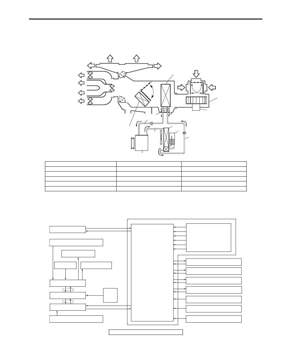
Air Conditioning System: 7B-8
Schematic and Routing Diagram
Air Flow Diagram of A/C System
S5JB0A7202003
Auto A/C Electronic Control Input / Output Diagram
S5JB0A7202004
13
13
14
14
15
15
7
2
12
11
1
3
11
9
10
4
8
5
6
16
17
I5JB0A720008-02
1. HVAC unit
7. Expansion valve
13. Defroster air
2. Evaporator
8. Liquid pipe
14. Demister air
3. Blower fan motor
9. Suction pipe
15. Foot air
4. Compressor
10. Discharge pipe
16. Ventilation air
5. Condenser assembly
11. Recirculation air
17. Heater core
6. Receiver / dryer
12. Fresh air
Sunload sensor
Outside air temperature sensor
Evaporator temperature sensor
A/C refrigerant pressure sensor
Temperature selector
MODE (air flow) selector
Blower speed selector
Air intake selector
AUTO switch
A/C switch
Compressor relay
Blower motor controller
Temperature control actuator
Air flow control actuator
Air intake control actuator
BCM
ECM
Data link connector
HVAC control module
CPU
ECT sensor
Inside air temperature sensor
ABS control module
Wheel
speed
sensor
Radiator fan relay
*
*
I5JB0A720004-05
*: CAN communication
7B-9 Air Conditioning System:
A/C System Wiring Circuit Diagram
S5JB0A7202002
12V
5V
M
12V
M
5V
5V
M
12V
12V
G52-1
G52-2
G52-8
G52-4
G52-15
G52-19
G52-20
12V
M
5V
5V
G52-21
G52-22
G52-23
G52-27
G52-28
G52-31
G52-32
G52-29
G52-30
G52-14
5V
5V
G52-18
G52-12
5V
12V
12V
5V
G52-13
G52-16
12V
5V
5V
12V
+BB
G52-17
G52-3
PPL/RED
WHT
RED/YEL
RED/WHT
WHT/BLK
BLU/BLK
BLK/RED
GRY
GRY/BLU
BLK/RED
WHT/RED
RED/WHT
ORN
GRN
RED/WHT
WHT/GRN
BLK/RED
GRY/RED
GRY/BLK
RED/WHT
WHT/BLU
BLK/RED
PNK
YEL
PPL/WHT
BLK
BLK/RED
RED/BLK
PPL/GRN
G52-10
G52-11
G52-6
G52-5
YEL/RED
PNK/GRN
PNK/BLK
RED/GRN
WHT/BLK
GRY/GRN
GRY/RED
GRY/BLK
M
M
RED/YEL
RED
RED/BLK
BLU/WHT
BLK
WHT/RED
BLK/RED
BLU/BLK
PNK
YEL/GRN
YEL/GRN
YEL/GRN
RED/GRN
*RED
BLU
BLU/WHT
BLU/BLK
RED
WHT
WHT/RED
WHT/BLU
BLK/RED
3
2
1
4
17
18
19
40
41
20
37
21
22
23
24
34
34
25
29
30
42
31
38
39
32
33
43
45
35
36
16
26
27
28
5
6
7
8
44
9
10
11
12
13
14
15
5V
I5JB0A720007-05
1. Battery
17. Compressor relay
33. Refrigerant pressure sensor
2. Main fuse
18. Rear defogger relay
34. To fuse box
3. Fuse box
19. Blower motor relay
35. Theft deterrent light
4. To radiator fan relay No.1
20. Rear defogger
36. Illumination lamp
5. To radiator fan relay No.3
21. A/C compressor
37. Indicator lamp, switch, selector
6. Ignition switch
22. Blower motor
38. To wheel speed sensor
7. Small lamp relay
23. Blower motor selector
39. To information display

Air Conditioning System: 7B-10
Component Location
A/C Control System Components Location
S5JB0A7203001
NOTE
The figure shows left-hand steering vehicle. For right-hand vehicle, parts with (*) are installed at the
opposite side.
8. To BCM
24. Radiator fan relay No.1
40. To ECM
9. Evaporator temperature sensor
25. Radiator fan No.1
41. To BCM
10. Inside air temperature sensor
26. Radiator fan relay No.2
42. To compressor relay
11. Temperature control actuator
27. Radiator fan relay No.3
43. To rear defogger relay
12. Air intake control actuator
28. Radiator fan No.2
44. To combination switch
13. Air flow control actuator
29. BCM
45. AUTO-ON head light system vehicle
14. Sunload sensor
30. Outside temperature sensor
*: M16 engine model
15. Data link connector
31. ABS control module
16. HVAC control module
32. ECM
Нет комментариевНе стесняйтесь поделиться с нами вашим ценным мнением.
Текст