Suzuki Grand Vitara JB416 / JB420. Manual — part 46

1A-133 Engine General Information and Diagnosis:
4
Was terminal “Vout” voltage in Step 3 within specification?
Go to Step 5.
“WHT/RED” wire is
open or shorted to
ground / power supply
circuit.
If wire and connection
are OK, substitute a
known-good ECM and
recheck.
5
Ground circuit check
1) Turn ignition switch to OFF position.
2) Measure resistance between “BLK/YEL” wire terminal of
CMP sensor connector and engine ground.
Is measured resistance value less than 3
Ω
?
Go to Step 6.
“BLK/YEL” wire is open
or high resistance
circuit.
6
Was terminal “B+” voltage in Step 3 within specification?
Go to Step 7.
“BLU/BLK” wire is open
circuit. If wire and
connection are OK,
substitute a known-
good ECM and recheck.
7
CMP sensor check
1) Check CMP sensor and signal rotor tooth referring to
“Camshaft Position (CMP) Sensor Inspection in Section
1C”.
Is check result satisfactory?
Substitute a known-
good ECM and recheck.
Replace CMP sensor
and/or intake camshaft.
Step
Action
Yes
No
Engine General Information and Diagnosis: 1A-134
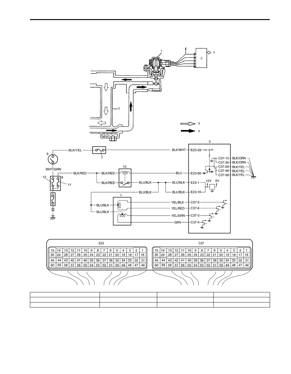
DTC P0401 / P0402: Exhaust Gas Recirculation Flow Insufficient Detected / Excessive Detected
S5JB0A1104042
System and Wiring Diagram
I5JB0A110051-01
1. EGR valve
4. Sensed information
7. “IG COIL” fuse
10. Main relay
2. Intake manifold
5. Fresh air
8. Fuse box No.2
11. “FI” fuse
3. ECM
6. Exhaust gas
9. Ignition switch
12. “IGN” fuse

1A-135 Engine General Information and Diagnosis:
DTC Detecting Condition and Trouble Area
DTC Confirmation Procedure
WARNING
!
• When performing a road test, select a place where there is no traffic or possibility of a traffic
accident and be very careful during testing to avoid occurrence of an accident.
• Road test should be carried out by 2 persons, a driver and a tester, on a level road.
NOTE
Check to make sure that following conditions are satisfied when using this “DTC confirmation
procedure”.
• Intake air temperature at engine start: –10
°C (14 °F) to 80 °C (176 °F)
• Intake air temperature: –10
°C (14 °F) to 70 °C (158 °F)
• Engine coolant temperature: 70
°C (158 °F) to 150 °C (302 °F)
• Altitude (barometric pressure): 2400 m, 8000 ft or less (560 mmHg, 75 kPa or more)
1) With ignition switch turned OFF, connect scan tool.
2) Turn ON ignition switch and clear DTC using scan tool.
3) Start engine and warm up to normal operating temperature.
4) Run engine at idle for 10 min.
5) Drive vehicle and increase engine speed 3000 rpm in 3rd gear.
6) Release accelerator pedal and with engine brake applied, keep vehicle coasting for 5 sec. or more. (Keep fuel cut
condition for 5 sec. or more) If fuel cut condition is not kept for 5 sec. or more, coast down a slope in engine speed
1000 – 3000 rpm for 5 sec. or more.
7) Stop vehicle and run engine at idle.
8) Check DTC and pending DTC by using scan tool.
DTC detecting condition
Trouble area
DTC P0401:
Difference in intake manifold absolute pressure between opened EGR valve
and closed EGR valve is smaller than specified value.
(*2 driving cycle detection logic, monitoring once / 1 driving)
DTC P0402:
Difference in intake manifold absolute pressure between opened EGR valve
and closed EGR valve is larger than specified value.
(*2 driving cycle detection logic, monitoring once / 1 driving)
• EGR valve
• EGR passage
• MAP sensor
• ECM

Engine General Information and Diagnosis: 1A-136
DTC Troubleshooting
NOTE
Before this trouble shooting is performed, read the precautions for DTC troubleshooting referring to
“Precautions For DTC Troubleshooting”.
Step
Action
Yes
No
1
Was “Engine and Emission Control System Check”
performed?
Go to Step 2.
Go to “Engine and
Emission Control
System Check”.
2
Do you have SUZUKI scan tool?
Go to Step 3.
Go to Step 5.
3
EGR valve operation check
1) With ignition switch turned OFF, install SUZUKI scan tool
to DTC.
2) Check EGR system referring to “EGR System Inspection
Is it in good condition?
Go to Step 4.
Go to Step 5.
4
MAP sensor check
1) Check MAP sensor for performance referring to
“Manifold Absolute Pressure (MAP) Sensor Inspection in
Section 1C”.
Is check result satisfactory?
Intermittent trouble or
faulty ECM.
Check for intermittent
referring to “Intermittent
and Poor Connection
Inspection in Section
00”.
Replace MAP sensor.
5
EGR valve control circuit check
1) Check that EGR valve control circuits are in good
condition referring to Step 2 to 5 of “DTC P0403:
Exhaust Gas Recirculation Control Circuit”
Are circuits in good condition?
Go to Step 6.
Repair or replace EGR
valve control circuit(s).
6
EGR valve check
1) Check EGR valve referring to “EGR Valve Inspection in
Is check result satisfactory?
Go to Step 7.
Faulty EGR valve.
7
MAP sensor check
1) Check MAP sensor for performance referring to
“Manifold Absolute Pressure (MAP) Sensor Inspection in
Section 1C”.
Is check result satisfactory?
EGR passage clogged.
If OK, substitute a
known-good ECM and
recheck.
Replace MAP sensor.
Нет комментариевНе стесняйтесь поделиться с нами вашим ценным мнением.
Текст