Suzuki Grand Vitara JB416 / JB420. Manual — part 235
5A-74 Automatic Transmission/Transaxle:
Inspection of TCM and Its Circuits
S5JB0A5104061
TCM and its circuits can be checked at TCM wiring connectors by measuring voltage, pulse signal and resistance.
CAUTION
!
TCM cannot be checked by itself, it is strictly prohibited to connect voltmeter or ohmmeter to TCM with
connector disconnected from it.
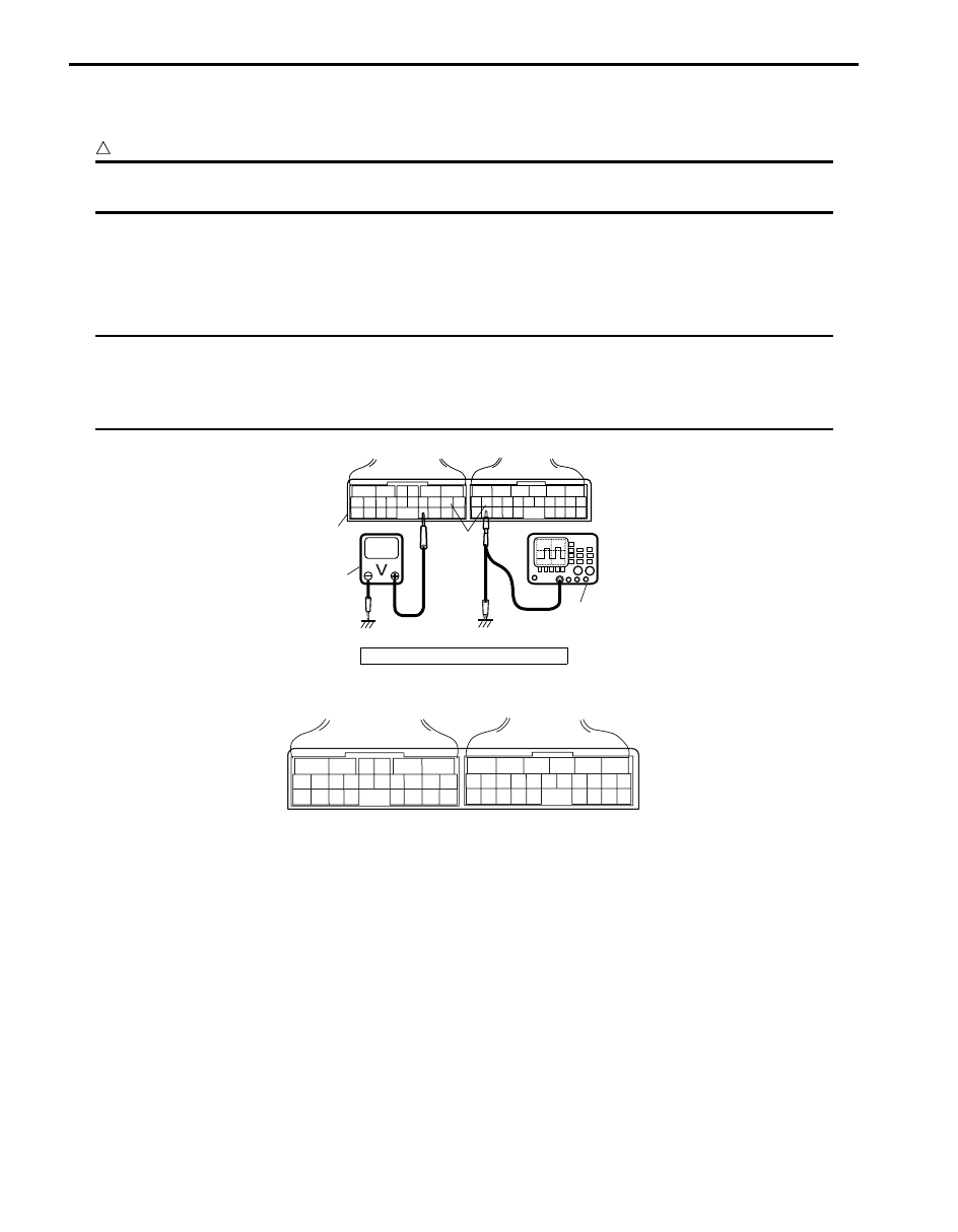
1) Remove TCM (1) from vehicle referring to “Transmission Control Module (TCM) Removal and Installation”.
2) Connect TCM connectors (2) to TCM.
3) Check voltage and/or pulse signal at each terminal of connectors connected using voltmeter (3) and oscilloscope
(4).
NOTE
• As each terminal voltage is affected by battery voltage, confirm that it is 11 V or more when ignition
switch is ON.
• Voltage with asterisk (*) cannot be measured by voltmeter because it is pulse signal. Check it with
oscilloscope if necessary.
Terminal arrangement of TCM coupler (Viewed from harness side)
3. Body ground
3
4
1
2
I4RS0A510021-02
6
5
16 15 14 13 12 11
4 3
24 23
21
22
10 9
8
7
2
1
19
20
18 17
E92
17 16
26 25
15 14
6
5
3
4
2
13 12
23 22
24
11 10 9
21 20 19
8 7
18
1
E93
I5JB0A510151-01
Automatic Transmission/Transaxle: 5A-75
Connector “E92”
Terminal Wire color
Circuit
Standard
voltage
Condition
1
BLK/ORN Ground
0 – 1 V
Ignition switch ON
2
BRN/RED
Pressure control
solenoid valve (–)
0.6 – 1.0 V Ignition switch ON
3
PPL/WHT
TCC pressure control
solenoid valve (–)
0.6 – 1.0 V Ignition switch ON
4
YEL/RED
Pressure control
solenoid valve (+)
*0 – 0.6 V
↑↓
10 – 14 V
Engine running at idling.
(Output signal is duty pulse. Duty ratio varies
depending on throttle valve opening.)
5
GRN/YEL
TCC pressure control
solenoid valve (+)
*0 – 0.6 V
↑↓
10 – 14 V
Engine running at idling.
(Output signal is duty pulse. Duty ratio varies
depending on torque converter clutch operating
condition.)
6
BLK/WHT Power source
10 – 14 V Ignition switch ON
7
WHT
CAN communication
line (Low)
*2.5 – 3.6 V
↑↓
1.6 – 2.5 V
Engine running at idling with after warming up.
(CAN communication signal is pulse. Pulse signal
frequency varies depending on engine condition.))
8
—
—
—
—
9
—
—
—
—
10
YEL/BLK
3 position switch (–)
0 – 1 V
Ignition switch ON
11
YEL/BLK
Transmission fluid
temperature sensor (+)
2.9 – 3.1 V Ignition switch ON, fluid temperature is 20
°C (68 °F)
0.3 – 0.5 V Ignition switch ON, fluid temperature is 100
°C (212 °F)
12
ORN
Transmission fluid
temperature sensor (–)
0 – 1 V
Ignition switch ON
13
—
—
—
—
14
—
—
—
—
15
GRN/RED
Shift solenoid valve-B
(No.2)
9 – 14 V
Ignition switch ON, select lever in “P” range
16
GRN
Shift solenoid valve-A
(No.1)
9 – 14 V
Ignition switch ON, select lever in “P” range
17
RED
CAN communication
line (High)
*2.5 – 3.6 V
↑↓
1.6 – 2.5 V
Engine running at idling with after warming up.
(CAN communication signal is pulse. Pulse signal
frequency varies depending on engine condition.)
18
—
—
—
—
19
—
—
—
—
20
YEL/RED 3 position switch (+)
2.4 – 4.3 V
Ignition switch ON, select lever in “P”, “R”, “N” or “D”
range
0.8 – 2.4 V Ignition switch ON, select lever in “3”, “2” or “L” range
21
—
—
—
—
22
—
—
—
—
23
BLK
Ground
0 – 1 V
Ignition switch ON
24
WHT
Power source for back-
up
10 – 14 V Constantly

5A-76 Automatic Transmission/Transaxle:
Connector “E93”
Terminal Wire color
Circuit
Standard
voltage
Condition
1
RED
Transmission range
sensor (“R” range)
8 – 14 V
Ignition switch ON, selector lever at “R” range
0 – 1 V
Ignition switch ON, selector lever at other than “R”
range
2
—
—
—
—
3
—
—
—
—
4
PNK/WHT 4L/N switch
8 – 14 V
Ignition switch ON, transfer position in 4H
0 – 1 V
Ignition switch OFF, transfer position in 4L and N
5
WHT
Output shaft speed
sensor (+)
0 – 1 V
Ignition switch ON, engine stops
While engine running.
(Output signal is waveform. Waveform frequency varies
depending on output shaft speed. (18 pulses are
generated par 1 input shaft revolution.))
6
BLU
Input shaft speed
sensor (+)
0 – 1 V
Ignition switch ON, engine stops.
While engine running.
(Output signal is waveform. Waveform frequency varies
depending on output shaft speed. (24 pulses are
generated par 1 input shaft revolution.))
7
GRN
Transmission range
sensor (“D” range)
8 – 14 V
Ignition switch ON, selector lever at “D” range
0 – 1 V
Ignition switch ON, selector lever at other than “D”
range
8
GRN/ORN
Transmission range
sensor (“N” range)
8 – 14 V
Ignition switch ON, selector lever at “N” range
0 – 1 V
Ignition switch ON, selector lever at other than “N”
range
9
—
—
—
—
10
—
—
—
—
11
—
—
—
—
12
PNK/BLK Diagnosis switch
8 – 14 V
Ignition switch ON
13
—
—
—
—
14
ORN
Output shaft speed
sensor (–)
2 – 3 V
Ignition switch ON, engine at stop
15
—
—
—
—
16
PNK
Input shaft speed
sensor (–)
2 – 3 V
Ignition switch ON, engine at stop
17
—
—
—
—
18
GRN/WHT
Transmission range
sensor (“L” range)
8 – 14 V
Ignition switch ON, selector lever at “L” range
0 – 1 V
Ignition switch ON, selector lever at other than “L”
range
19
GRN/ORN
Transmission range
sensor (“2” range)
8 – 14 V
Ignition switch ON, selector lever at “2” range
0 – 1 V
Ignition switch ON, selector lever at other than “2”
range
20
PNK
Transmission range
sensor (“P” range)
8 – 14 V
Ignition switch ON, selector lever at “P” range
0 – 1 V
Ignition switch ON, selector lever at other than “P”
range
21
—
—
—
—
22
—
—
—
—
23
PPL/WHT Data link connector
8 – 14 V
Ignition switch ON
24
—
—
—
—
25
—
—
—
—
26
—
—
—
—
Automatic Transmission/Transaxle: 5A-77
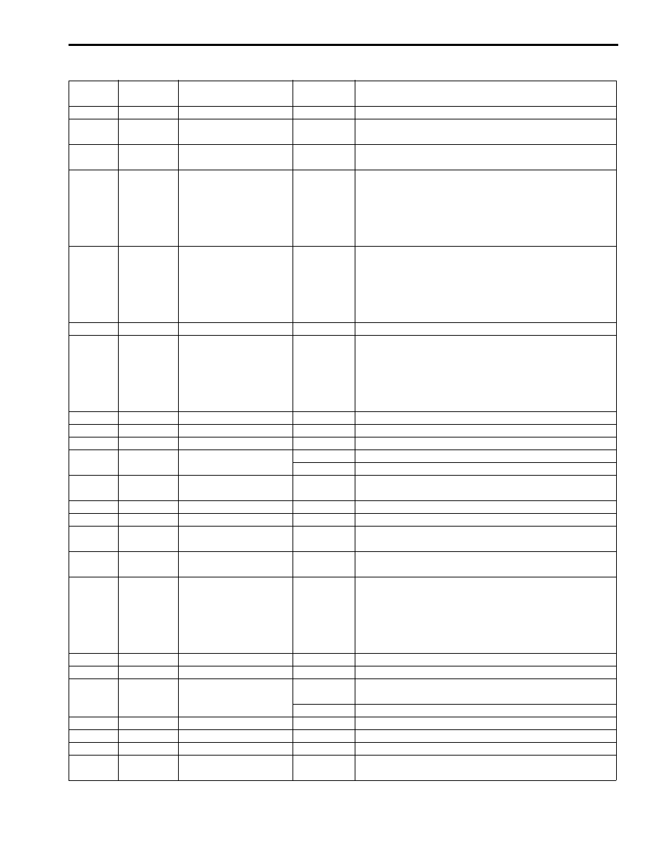
Reference Waveform No. 1
Pressure control solenoid valve signal at engine idling.
Reference Waveform No. 2
TCC pressure control solenoid valve signal at engine
idling.
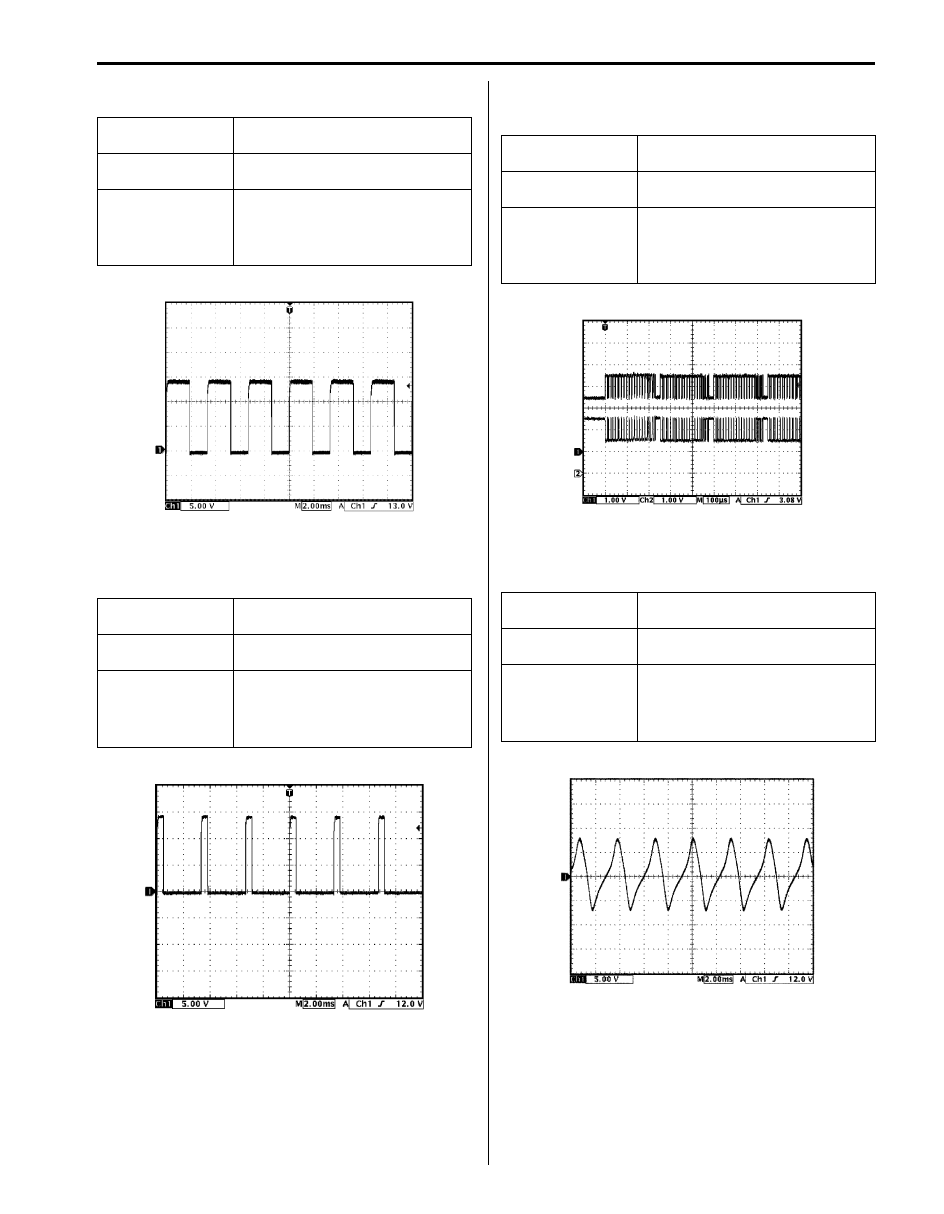
Reference Waveform No. 3
CAN communication line (High & Low) signal at engine
idling.
Reference Waveform No. 4
Output shaft speed sensor signal at vehicle speed 40
km/h (25 mile/h).
Measurement
terminal
CH1: “E92-4” to “E92-1”
Oscilloscope
setting
CH1: 5 V/DIV
TIME: 20 ms/DIV
Measurement
condition
• After warmed up to normal
operating temperature
• Engine at specified idle speed
with “P” range.
Measurement
terminal
CH1: “E92-5” to “E92-1”
Oscilloscope
setting
CH1: 5 V/DIV
Time: 2 ms/DIV
Measurement
condition
• After warmed up to normal
operating temperature
• Engine at specified idle speed
with “P” range
I3RM0B510029-01
I4RS0A510024-01
Measurement
terminal
CH1: “E92-7” to “E92-1”
CH2: “E92-17” to “E92-1”
Oscilloscope
setting
CH1: 1 V/DIV
TIME: 100
µs/DIV
Measurement
condition
• After warmed up to normal
operating temperature
• Engine at specified idle speed
with “P” range.
Measurement
terminal
CH1: “E93-5” to “E92-1”
Oscilloscope
setting
CH1: 5 V/DIV
TIME: 2 ms/DIV
Measurement
condition
• After warmed up to normal
operating temperature
• Drive vehicle at 40 km/h (25
mile/h).
I3RM0B510030-01
I5JB0A510046-02
Нет комментариевНе стесняйтесь поделиться с нами вашим ценным мнением.
Текст