Suzuki Grand Vitara JB416 / JB420. Manual — part 282

7B-19 Air Conditioning System:
Scan Tool Data
S5JB0A7204032
As the data values given below are standard values estimated on the basis of values obtained from the normally
operating vehicles by using a scan tool, use them as reference values. Even when the vehicles are in good condition,
there may be cases where the checked values do not fall within each specifies data range. Therefore, judgement as
abnormal should not be made by checking with these data alone.
B1551 Serial communication circuit
malfunction
HVAC control module keeps
condition just before malfunction is
detected.
HVAC control module controls
actuators assuming that as follows.
• Outside air temperature is 20
°C (68
°F).
• Engine coolant temperature is 90
°C
(194
°F).
• Vehicle speed is 0 km/h (0 mph).
• Engine speed is 0 rpm.
B1552
B1553
CAN communication circuit
malfunction
B1556
Camshaft position (CMP)
sensor and/or its circuit
malfunction
HVAC control module keeps
condition just before malfunction is
detected.
HVAC control module controls
actuators assuming that amount of
engine speed is 0 rpm.
B1557
Vehicle speed sensor and/
or its circuit malfunction
HVAC control module keeps
condition just before malfunction is
detected.
HVAC control module controls
actuators assuming that amount of
vehicle speed is 0 km/h (0 mph).
B1561
Engine coolant temperature
sensor and/or its circuit
malfunction
HVAC control module keeps
condition just before malfunction is
detected.
HVAC control module controls
actuators assuming that amount of
engine coolant temperature is 90
°C
(194
°F).
B1562
Outside air temperature
sensor and/or its circuit
malfunction
HVAC control module keeps
condition just before malfunction is
detected.
HVAC control module controls
actuators assuming that amount of
outside air temperature is 20
°C (68
°F).
DTC No.
Trouble Area
Fail-Safe Operation
When ignition switch is turned
ON after malfunction is already
detected
When malfunction is detected
during ignition switch is ON
Scan Tool Data
Condition
Normal Condition /
Reference Value
TEMP CONT SWITCH
Each reference value is relative to the position of
temperature selector of HVAC control module.
Max Cool, 18
°C (64.4 °F)
– 28
°C (82.4 °F), Max Hot
CABIN TEMPERATURE
Reference value is relative to in car temperature.
–40
°C – 87.5 °C
(–40
°F – 189.5 °F)
OUT SIDE AIR TEMP
Reference value is relative to outside air temperature.
–40
°C – 87.5 °C
(–40
°F – 189.5 °F)
EVAPORATOR TEMP
Reference value is relative to temperature of evaporator.
–40
°C – 87.5 °C
(–40
°F – 189.5 °F)
COOLANT TEMP
At specified idle speed after warming up
–40
°C – 215 °C
(–40
°F – 419 °F)
SUN LOAD
Reference value depends on the situation.
0 W/m
2
– 4447.8 W/m
2
MODE CONT SWITCH
Each reference value is relative to the position of airflow
selector of HVAC control module.
AUTO, VENT, BI-LEVEL,
FOOT, DEF-FOOT DEF
FAN CONT SWITCH
Each reference value is relative to the position of blower
speed selector of HVAC control module.
AUTO, OFF 1st, 2nd – 7th,
8th
FAN DESIRE VOLT
Reference value is relative to the position of blower
speed selector of HVAC control module.
0 – 16.0 V
AIR MIX POS SENSOR
Reference value is relative to the position of temperature
selector of HVAC control module.
Approx. 1.5 V (Max Hot)
Approx. 4.5 V (Max Cool)
R/F POS SENSOR
Reference value is relative to the position of air intake
selector of HVAC control module. (LH steering vehicle)
Approx. 4.0 V (REC)
Approx. 0.9 V (FRE)
R/F POS SENSER
Reference value is relative to the position of air intake
selector of HVAC control module. (RH steering vehicle)
Approx. 0.9 V (REC)
Approx. 4.0 V (FRE)

Air Conditioning System: 7B-20
Scan Tool Data Definitions
TEMP CONT SWITCH: Position of temperature control
selector of HVAC control module
CABIN TEMPERATURE: In-car temperature detected
by inside air temperature sensor installed in HVAC
control module
OUTSIDE AIR TEMP (OUTSIDE AIR
TEMPERATURE): Outside air temperature
detected by outside air temperature sensor installed
in front bumper member
EVAPORATOR TEMP: Temperature of air passed
through evaporator
COOLANT TEMP: Engine coolant temperature
detected by engine coolant temperature sensor
SUN LOAD: Amount of sunlight detected by sunload
sensor installed on the driver side on the dashboard
MODE CONT SWITCH: Position of airflow selector of
HVAC control module
FAN CONT SWITCH: Position of air speed selector of
HVAC control module
FAN DESIRE VOLT: Voltage for blower motor
AIR MIX POS SENSOR: Input signal from position
sensor in temperature control actuator
MODE POS SENSOR: Input signal form position
sensor in air flow control actuator
R/F POS SENSOR (AIR FLOW CONTROL ACTUATOR
POSITION SENSOR): Input signal from position
sensor in air intake control actuator
A/C CONT SIG (ON or OFF): State of A/C indicator
lamp
AIR INTAKE MODE (FRE, REC or MIX): State of air
intake mode
A/C COMP CLUCH: State of magnet clutch
REFRIGERANT PRESSURE (A/C REFRIGERANT
ABSOLUTE PRESSURE): This parameter
indicates A/C refrigerant absolute pressure
calculated by ECM
A/C INDICATOR LAMP (ON or OFF): State of A/C
indicator lamp
FRE INDICATOR LAMP (ON or OFF): State of fresh air
(FRE) indicator lamp
REC INDICATOR LAMP (ON or OFF): State of
recirculation air (REC) indicator lamp
REAR DEF INDICATOR (ON or OFF): State of rear
defogger indicator lamp
VEHICLE SPEED: It is computed based on pulse
signals from vehicle speed sensor
ENGINE SPEED: It is computed by signal from CMP
sensor
MODE POS SENSOR
Reference value is relative to the position of airflow
selector of HVAC control module.
Approx. 0.5 V (DEF)
Approx. 4.5 V (VENT)
A/C CONT SIG
A/C system is ON.
ON
A/C system is OFF.
OFF
AIR INTAKE MODE
Fresh air (FRE) mode is activated.
FRE
Recirculation air (REC) mode is activated.
REC
AUTO mode is activated.
AUTO
A/C COMP CLUCH
Magnet clutch is engaged.
ON
Magnet clutch is not engaged.
OFF
REFRIGERANT PRESSURE
Engine
running.
A/C ON (A/C is operating) at ambient
temperature: 30
°C (86 °F)
1350 – 1650 kPa for more
details, refer to pressure of
high pressure gauge under
A/C ON (A/C is not operating) at ambient
temperature: 30
°C (86 °F) and engine coolant
temperature: 90
°C – 100 °C (194 °F – 212 °F)
600 – 1000 kPa after
longer than 10 min from A/
C switch turned off.
A/C INDICATOR LAMP
A/C indicator lamp is lighted.
ON
A/C indicator lamp is not lighted.
OFF
FRE INDICATOR LAMP
Fresh air (FRE) indicator lamp is lighted.
ON
Fresh air (FRE) indicator lamp is not lighted.
OFF
REC INDICATOR LAMP
Recirculation air (REC) indicator lamp is lighted.
ON
Recirculation air (REC) indicator lamp is not lighted.
OFF
REAR DEF INDICATOR
Rear defogger indicator lamp is lighted.
ON
Rear defogger indicator lamp is not lighted.
OFF
VEHICLE SPEED
At stop.
0 km/h (0 mph)
ENGINE SPEED
At engine idle speed
Engine idle speed is
display
Scan Tool Data
Condition
Normal Condition /
Reference Value

7B-21 Air Conditioning System:
Visual Inspection
S5JB0A7204008
Visually check the following parts and systems.
A/C System Performance Inspection
S5JB0A7204027
1) Confirm that vehicle and environmental conditions
are as follows.
• Vehicle is put indoors.
• Ambient air temperature is within 15 – 35
°C (59 –
95
°F).
• Relative humidity is within 30 – 70%.
• There is no wind indoors.
• HVAC unit is normal condition.
• There is no air leakage from air ducts.
• Condenser fins are clean.
• Are filter is not clogged with dirt and dust.
• Battery voltage is 12 V or more.
• Radiator cooling fan operates normally.
2) Make sure that high pressure valve (1) and low
pressure valve (2) of manifold gauge (3) are firmly
closed.
3) Connect high pressure charging hose (4) to high
pressure service valve (5) on vehicle, and connect
low pressure charging hose (6) to low pressure
service valve (7) on vehicle.
4) Bleed the air in charging hoses by loosening their
respective nuts on manifold gauge, utilizing the
refrigerant pressure. When a hiss is heard,
immediately tighten nut.
CAUTION
!
Do not interchange high and low pressure
charging hoses by mistake.
5) Warm up engine to normal operating temperature
(engine coolant temperature at 80 – 90
°C (176 –
194
°F)) and keep it at specified idle speed.
6) Operate A/C at the following conditions.
• A/C switch at ON position
• Blower speed selector at max position
• Air flow selector at “VENT” position
• Temperature selector at max cool position
• Vehicle door at all open
• Air inlet door at recirculation position
Inspection Item
Correction
• Refrigerant ---- leakage and amount
• A/C pipe or hose ---- disconnection, looseness and
deterioration
• A/C compressor drive belt ---- looseness and damage
• Battery ---- fluid level and corrosion of terminal
• Connectors of electric wire harness ---- disconnection and
friction
• Fuses ---- burning
• Parts ---- installation and damage
• Other parts that can be checked visually
Refer to “A/C Compressor Drive Belt Inspection
and Adjustment”.
3
7
4
1
2
6
5
I5JB0A720010-01
Air Conditioning System: 7B-22
7) Wait for ten minutes to stabilize A/C operation.
8) Keep all windows, doors and engine food open.
9) With about 20 mm (0.8 in.) of dry bulb thermometer
(1) put right in front of center ventilation louver and a
wet and dry bulb thermometer (2) near air inlet (3) of
HVAC unit.
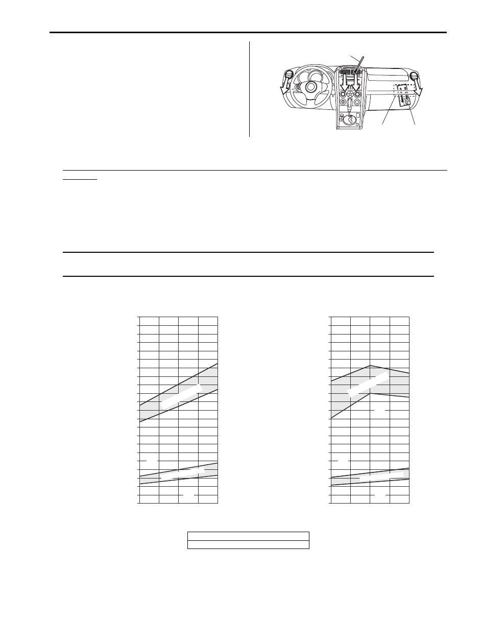
10) Check for each pressure of low side and high side if it is within shaded range of graph. If each gauge reading is out
of specified pressure, correct defective part referring to the table.
Low side and high side pressure example, gauges should read as follows when ambient temperature is 30
°C (86 °F)
M16 engine model
Pressure on high pressure gauge (HI): 1150 – 1410 kPa (11.5 – 14.1 kg/cm
2
, 164 – 201 psi)
Pressure on high pressure gauge (LO): 280 – 410 kPa (2.8 – 4.1 kg/cm
2
, 40 – 58 psi)
J20 engine model
Pressure on high pressure gauge (HI): 1300 – 1630 kPa (13.0 – 16.3 kg/cm
2
, 185 – 232 psi)
Pressure on high pressure gauge (LO): 250 – 370 kPa (2.5 – 3.7 kg/cm
2
, 36 – 53 psi)
NOTE
Pressure registered on gauge varies with ambient temperature. Therefore, use the graphs when
determining if pressures are normal or not.
1
3
2
I5JB0A720011-01
[A]
[B]
14.2
28.4
Pressure of Lo
Pressure Gauge
22
312.9
2200
0
1
2
3
30
70
30
70
%
4
5
6
7
8
9
10
11
12
13
14
15
16
17
18
19
21
298.7
2100
20
42.7
56.9
71.1
85.3
99.5
113.8
128.0
142.2
151.4
170.6
184.9
199.1
213.3
227.5
241.7
256.0
270.2
284.4
100
200
300
400
500
600
700
800
900
1000
1100
1200
1300
1400
1500
1600
1700
1800
1900
2000
25
30
35
77
86
95
psi
kPa kg/cm
2
Ambient Temperature
C
F
w
Pressure of High Pressure
Gauge
“A”
“B”
“C”
“D”
Acceptab
le r
ange
Humidity
Acceptab
le range
14.2
28.4
Pressure of Lo
Pressure Gauge
22
312.9
2200
0
1
2
3
30
70
30
70
%
4
5
6
7
8
9
10
11
12
13
14
15
16
17
18
19
21
298.7
2100
20
42.7
56.9
71.1
85.3
99.5
113.8
128.0
142.2
151.4
170.6
184.9
199.1
213.3
227.5
241.7
256.0
270.2
284.4
100
200
300
400
500
600
700
800
900
1000
1100
1200
1300
1400
1500
1600
1700
1800
1900
2000
25
30
35
77
86
95
psi
kPa kg/cm
2
Ambient Temperature
C
F
w
Pressure of High Pressure
Gauge
“A”
“B”
“C”
“D”
Humidity
Acceptab
le range
Acceptab
le r
ange
I5JB0A720012-04
[A]: M16 engine model
[B]: J20 engine model
Нет комментариевНе стесняйтесь поделиться с нами вашим ценным мнением.
Текст