Suzuki Grand Vitara JB416 / JB420. Manual — part 281
7B-15 Air Conditioning System:
5) After completing above check, turn ignition switch to
“OFF” position.
NOTE
HVAC control module returns to a original
state at the following conditions.
• Ignition switch turned to “OFF” position
• Temperature selector is operated
• Blower speed selector is operated
• 5 minutes have passed since HVAC control
unit started DTC display
DTC Clearance
S5JB0A7204029
Using SUZUKI Scan Tool
1) Turn ignition switch to OFF position.
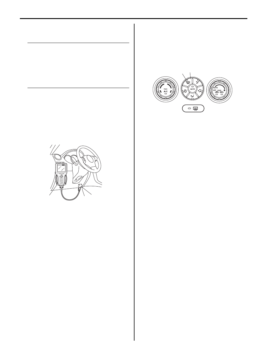
2) Connect SUZUKI scan tool to data link connector
(DLC) (1).
Special tool
(A): SUZUKI scan tool
3) Turn ignition switch to ON position.
4) Erase DTC according to instructions displayed on
SUZUKI scan tool. Refer to SUZUKI scan tool
operator’s manual for further details.
5) After completing the clearance, turn ignition switch to
OFF position and disconnect SUZUKI scan tool from
DLC.
6) Perform “DTC Check” and confirm if normal DTC
(NO CODES) is displayed.
Not Using SUZUKI Scan Tool
1) Display history DTC by HVAC control module
referring to “Not Using SUZUKI Scan Tool” under
“DTC Check”.
2) Confirm display DTC and light “DEF” indicator lamp
(1).
3) Push “DEF” switch (2) at 5 seconds or more.
4) After completing the clearance, turn ignition switch
OFF position.
5) Perform “DTC Check”, and confirm if normal DTC is
displayed and if any other DTC is detected.
(A)
1
I5JB0A720014-01
1
2
I5JB0A720016-03
Air Conditioning System: 7B-16
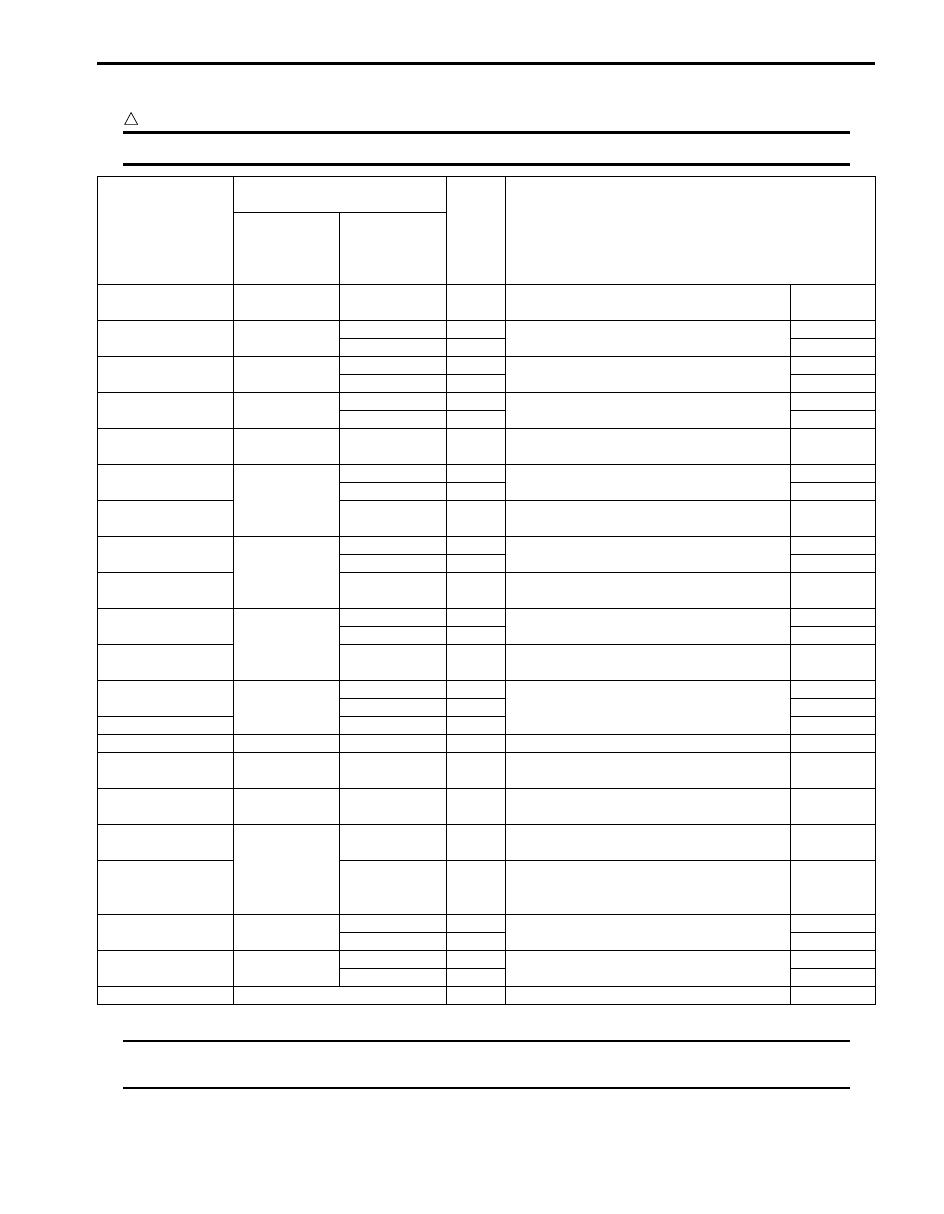
DTC Table
S5JB0A7204030
CAUTION
!
Be sure to perform “Air Conditioning System Check” before starting diagnosis.
NOTE
When no abnormality is detected, “FRE” indicator lamp and “REC” indicator lamp repeat cycle of ON
for 2 seconds and OFF for 1 second.
DTC No.
(displayed on
SUZUKI scan tool)
DTC (indicated on HVAC
control module)
Priority
of
display
Diagnosis
Indicated by
“REC”
indicator
lamp
Indicated by
“FRE”
indicator
lamp
B1562
1
4
1
Outside air temperature sensor and/or its
circuit malfunction
Data error
B1502
2
1
2
Inside air temperature sensor and/or its
circuit malfunction
Open
2
3
Short
B1503
3
1
4
Evaporator temperature sensor and/or its
circuit malfunction
Open
2
5
Short
B1504
4
1
29
Sunload sensor and/or its circuit
malfunction
Open
2
6
Short
B1561
5
4
7
Engine coolant temperature sensor and/or
its circuit malfunction
Data error
B1511
6
1
8
Temperature control actuator (position
sensor) and/or its circuit malfunction
Open
2
9
Short
B1513
3
10
Temperature control actuator and/or its
circuit malfunction
Lock detect
B1512
7
1
11
Air flow control actuator (position sensor)
and/or its circuit malfunction
Open
2
12
Short
B1514
3
13
Air flow control actuator and/or its circuit
malfunction
Lock detect
B1530
8
1
14
Air intake control actuator (position
sensor) and/or its circuit malfunction
Open
2
15
Short
B1531
3
16
Air intake control actuator and/or its circuit
malfunction
Lock detect
B1551
9
1
17
Serial communication circuit malfunction
Open
2
18
Short
B1552
4
19
Data error
B1553
10
4
20
CAN communication circuit malfunction
Data error
B1557
11
4
21
Wheel speed sensor and/or its circuit
malfunction
Data error
B1556
12
4
22
Camshaft position (CMP) sensor and/or its
circuit malfunction
Data error
B1563
13
4
23
A/C refrigerant pressure sensor and/or its
circuit malfunction
Data error
B1546
5
24
A/C refrigerant pressure sensor
malfunction
Refrigerant
pressure
malfunction
B1520
15
1
25
Temperature selector malfunction
Open
2
26
Short
B1521
16
1
27
Blower speed selector malfunction
Open
2
28
Short
—
See NOTE below
—
Normal
—
7B-17 Air Conditioning System:
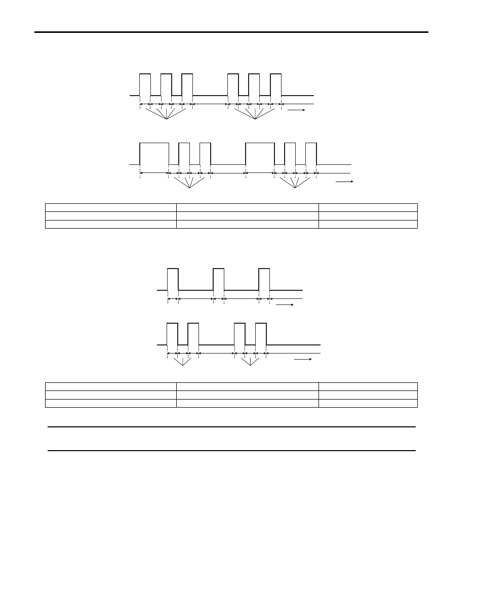
Example of “REC” Indicator Lamp Flashing Pattern
Example of “FRE” Indicator Lamp Flashing Pattern
NOTE
Locked actuator, data error and refrigerant pressure malfunction are indicated by flashing pattern of
“FRE” indicator lamp specified for each of them.
[A]
(a)
(b)
(d)
(c)
(e)
(d)
[B]
(a)
(b)
(d)
(c)
(e)
(f)
(f)
(d)
I5JB0A720017-01
[A]: B1503 (No.3)
(b): “REC” indicator lamp “OFF”
(e): 2.0 (sec.)
[B]: B1556 (No.12)
(c): Time (sec.)
(f): 1.5 (sec.)
(a): “REC” indicator lamp “ON”
(d): 0.5 (sec.)
[A]: Open
(b): “FRE” indicator lamp “OFF”
(e): 2.0 (sec.)
[B]: Short
(c): Time (sec.)
(a): “FRE” indicator lamp “ON”
(d): 0.5 (sec.)
[A]
(a)
(b)
[B]
(a)
(b)
(d)
(e)
(e)
(c)
(d)
(e)
(c)
(d)
(d)
I5JB0A720018-01
Air Conditioning System: 7B-18
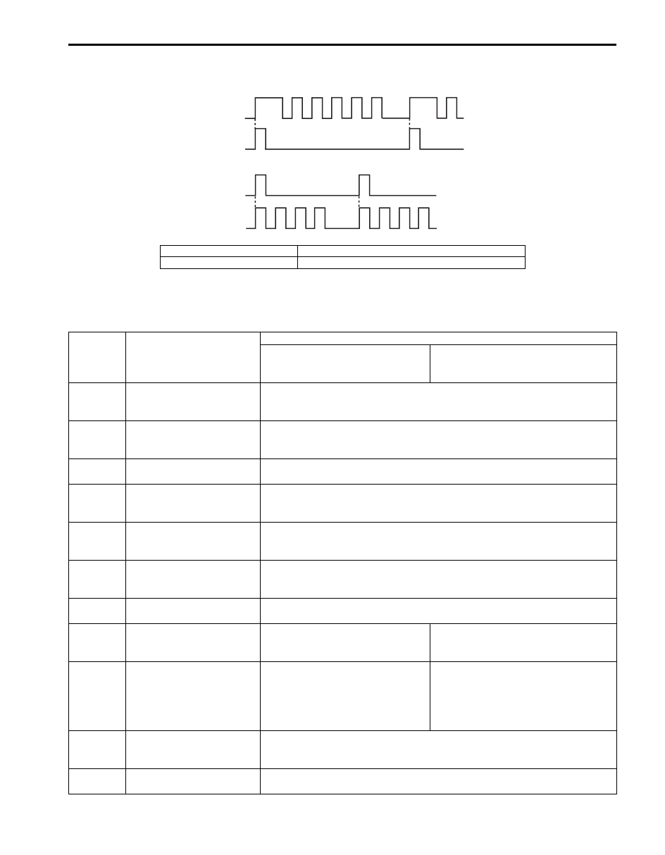
Display Timing of “FRE” Indicator Lamp and “REC” Indicator Lamp
Code with short display time waits until display of code with long display time is over.
Fail-Safe Table
S5JB0A7204031
When any of the following malfunctions (DTCs) is detected, HVAC control module enters fail-safe mode.
However, when HVAC control module detects normal operation of A/C system, fail-safe mode is canceled.
[A]: B1520 (15 – 1)
(a): “REC” indicator flashing pattern
[B]: B1562 (1 – 4)
(b): “FRE” indicator flashing pattern
[A]
(a)
(b)
[B]
(a)
(b)
I5JB0A720019-02
DTC No.
Trouble Area
Fail-Safe Operation
When ignition switch is turned
ON after malfunction is already
detected
When malfunction is detected
during ignition switch is ON
Inside air temperature
sensor and/or its circuit
malfunction
HVAC control module controls actuators assuming that inside air
temperature is 25
°C (77 °F).
Evaporator temperature
sensor and/or its circuit
malefaction
HVAC control module controls actuators assuming that amount of
evaporator temperature is –6
°C (21.2 °F).
Sunload sensor and/or its
circuit malfunction
HVAC control module controls actuators assuming that amount of sunlight is
0 W/m
2
.
B1511
Temperature control
actuator (position sensor)
and/or its circuit malfunction
Circuit open: Temperature control actuator fixed to “MAX HOT” position.
Circuit short: Temperature control actuator fixed to “MAX COOL” position.
Air flow control actuator
(position sensor) and/or its
circuit malfunction
Circuit open: Air flow control actuator fixed to “DEF” position.
Circuit short: Air flow control actuator fixed to “VENT” position.
Temperature control
actuator and/or its circuit
malfunction
Stop the operation of temperature control actuator.
Air flow control actuator
and/or its circuit malfunction
Stop the operation of Air flow control actuator.
Temperature selector
malfunction
HVAC control module keeps
condition just before malfunction is
detected.
HVAC control module controls
actuators assuming that setting of
temperature selector is 23
°C (73.4 °F).
Blower speed selector
malfunction
HVAC control module keeps
condition just before malfunction is
detected.
HVAC control module controls
actuators assuming that as follows.
• Blower speed is minimum.
• Air flow control actuator fixed to
“DEF” position.
Air intake control actuator
(position sensor) and/or its
circuit malfunction
Circuit open: Air intake control actuator fixed to “FRE” position.
Circuit short: Air intake control actuator fixed to “REC” position.
Air intake control actuator
and/or its circuit malfunction
Stop the operation of temperature control actuator.
Нет комментариевНе стесняйтесь поделиться с нами вашим ценным мнением.
Текст