Suzuki Grand Vitara JB416 / JB420. Manual — part 47
1A-137 Engine General Information and Diagnosis:
DTC P0403: Exhaust Gas Recirculation Control Circuit
S5JB0A1104043
Wiring Diagram
Refer to “DTC P0401 / P0402: Exhaust Gas Recirculation Flow Insufficient Detected / Excessive Detected”.
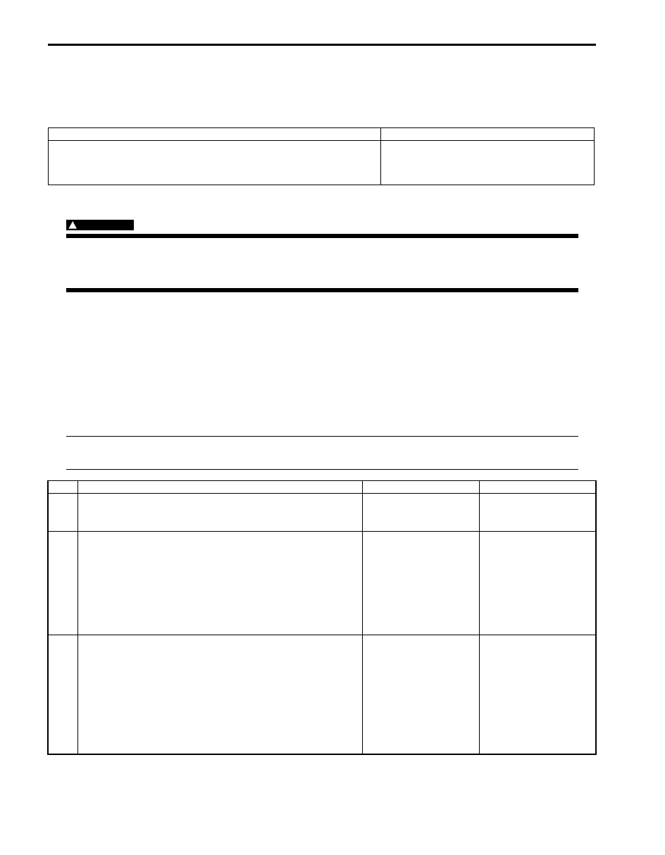
DTC Detecting Condition and Trouble Area
DTC Confirmation Procedure
WARNING
!
• When performing a road test, select a place where there is no traffic or possibility of a traffic
accident and be very careful during testing to avoid occurrence of an accident.
• Road test should be carried out by 2 persons, a driver and a tester, on a level road.
1) With ignition switch turned OFF, connect scan tool to DLC.
2) Turn ON ignition switch and clear DTC using scan tool.
3) Start engine and warm it up to normal operating temperature.
4) Drive vehicle in 2000 – 3500 rpm of engine speed.
5) Keep above vehicle speed for 1 min. (Throttle valve opening is kept constant in this step.)
6) Stop vehicle and check DTC and pending DTC.
DTC Troubleshooting
NOTE
Before this trouble shooting is performed, read the precautions for DTC troubleshooting referring to
“Precautions For DTC Troubleshooting”.
DTC detecting condition
Trouble area
EGR valve output voltage is different from output command with more
than one pole out of 4 poles.
(1 driving cycle detection logic)
• EGR valve circuit open
• EGR valve
• ECM
Step
Action
Yes
No
1
Was “Engine and Emission Control System Check”
performed?
Go to Step 2.
Go to “Engine and
Emission Control
System Check”.
2
EGR valve power supply circuit check
1) With ignition switch turned OFF, disconnect EGR valve
connector.
2) With ignition switch turned ON, measure voltage
between “BLU/BLK” wire terminal of EGR valve
connector and vehicle body ground.
Is check voltage 10 – 14 V?
Go to Step 3.
“BLU/BLK” wire is open
circuit.
3
Wire circuit check
1) Disconnect connectors from ECM with ignition switch
turned OFF.
2) Turn ON ignition switch.
3) Measure voltage between engine ground and each
“YEL/BLK”, “YEL/RED”, “YEL/GRN”, “YEL” wire
terminals of EGR valve connector.
Is each voltage 0 V?
Go to Step 4.
Faulty wire(s) are
shorted to other circuit.
If wires are OK,
substitute a known-
good ECM and recheck.

Engine General Information and Diagnosis: 1A-138
4
Wire circuit check
1) With ignition switch turned OFF, measure resistance
between engine ground and each “YEL/BLK”, “YEL/
RED”, “YEL/GRN”, “YEL” wire terminals of EGR valve
connector.
Is resistance infinity?
Go to Step 5.
Faulty wire(s) are
shorted to ground
circuit.
If wires are OK,
substitute a known-
good ECM and recheck.
5
Short circuit check for EGR valve control circuit
1) With ignition turned OFF, measure resistance between
each EGR valve control circuit wire (“YEL/BLK”, “YEL/
RED”, “YEL/GRN” and “YEL” wire) and each EGR valve
control circuit wire.
Is each resistance infinity?
Go to Step 6.
Faulty wire(s) are short
circuit.
6
EGR valve stepper motor coil circuit check
1) With ignition switch turned OFF, connect EGR valve
connector.
2) Measure resistance between “E23-1/16” and each “C37-
3”, “C37-4”, “C37-5”, “C37-6” terminals of ECM
connector.
Is each resistance 20 – 31
Ω
at 20
°
C, 68
°
F?
Faulty ECM. Substitute
a known-good ECM and
recheck.
Go to Step 7.
7
EGR valve check
1) Check EGR valve resistance referring to “EGR Valve
Is resistance within specified value?
Faulty wire(s) are open
or high resistance
circuit. If wires are OK,
substitute a known-
good ECM and recheck.
Faulty EGR valve.
Step
Action
Yes
No
1A-139 Engine General Information and Diagnosis:
DTC P0420: Catalyst System Efficiency below Threshold
S5JB0A1104044
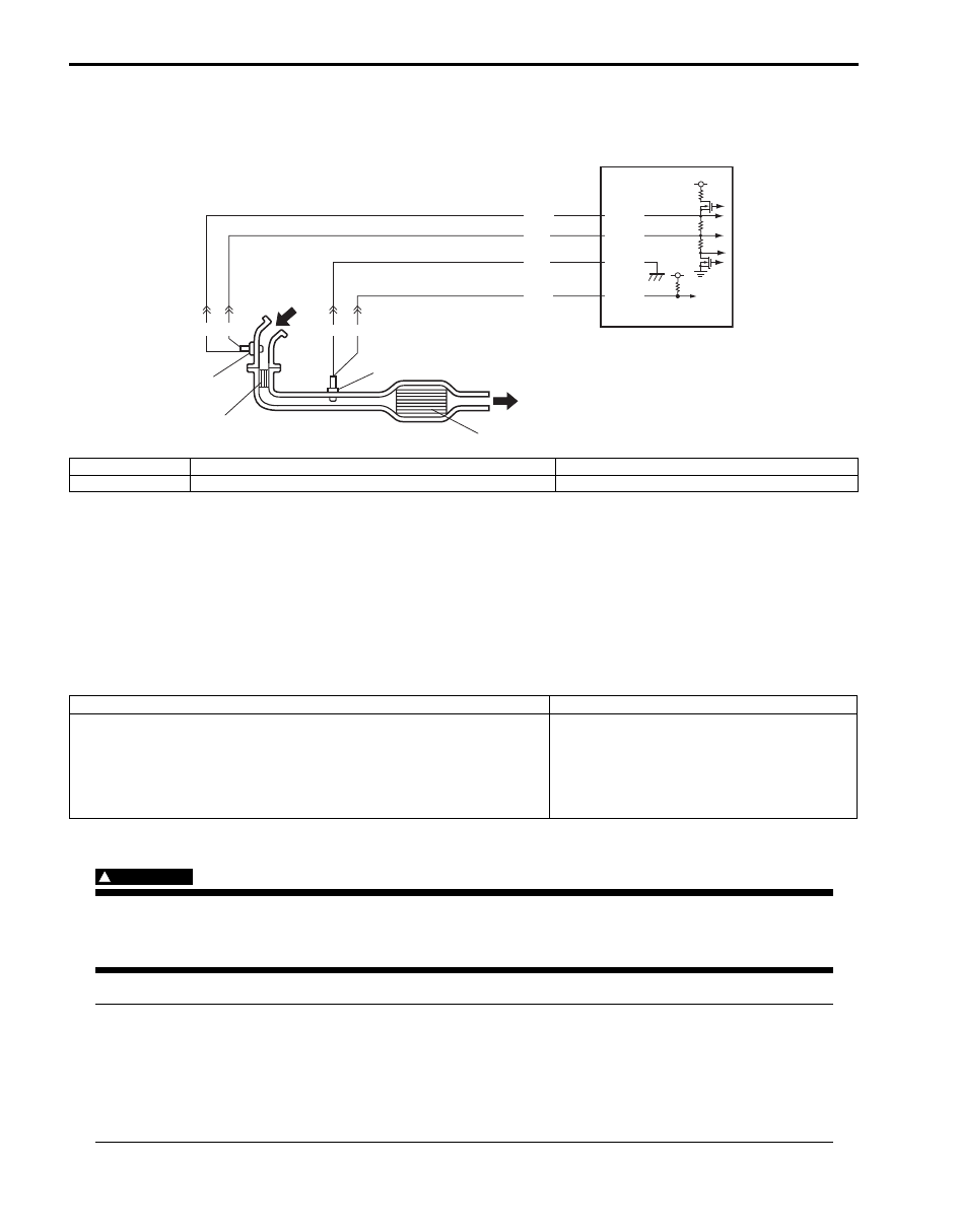
System and Wiring Diagram
Circuit Description
ECM monitors oxygen concentration in the exhaust gas which has passed the warm up three way catalytic converter
by HO2S-2. When the catalyst is functioning properly, the variation cycle of HO2S-2 output voltage (oxygen
concentration) is slower than that of A/F sensor output signal because of the amount of oxygen in the exhaust gas
which has been stored in warm up three way catalytic converter.
A/F Sensor Description
Refer to “A/F Sensor Description”.
DTC Detecting Condition and Trouble Area
DTC Confirmation Procedure
WARNING
!
• When performing a road test, select a place where there is no traffic or possibility of a traffic
accident and be very careful during testing to avoid occurrence of an accident.
• Road test should be carried out by 2 persons, a driver and a tester, on a level road.
NOTE
Check to make sure that following conditions are satisfied when using this “DTC Confirmation
Procedure”.
• Intake air temperature at engine start: –10
°C (14 °F) to 80 °C (176 °F)
• Intake air temperature: –10
°C (14 °F) to 70 °C (158 °F)
• Engine coolant temperature: 70
°C (158 °F) to 150 °C (302 °F)
• Altitude (barometric pressure): 2400 m, 8000 ft or less (560 mmHg, 75 kPa or more)
C37-11
C37-38
C37-57
WHT
BRN
1
3
2
4
5 V
YEL
BLU
WHT
BLU WHT
C37-37
BLK
5
5 V
I5JB0A110053-02
1. A/F sensor
3. Warm up three way catalytic converter
5. ECM
2. HO2S-2
4. Three way catalytic converter
DTC detecting condition
Trouble area
Ratio of integrated value of HO2S-2 output variation per integrated
value of A/F sensor output variation is more than specification while
vehicle is running constant speed and low engine load after warmed
up.
(*2 driving cycle detection logic, monitoring once / 1 driving)
• Exhaust gas leak
• Warm up three way catalytic converter
malfunction
• HO2S-2 malfunction
• A/F sensor malfunction

Engine General Information and Diagnosis: 1A-140
1) Connect scan tool to DLC with ignition switch turned OFF.
2) Turn ON ignition switch and clear DTC using scan tool.
3) Increase vehicle speed to 50 – 60 mph, 80 – 100 km/h. (engine speed: 2500 – 3000 r/min.)
4) Keep above vehicle speed for 10 min. or more (Throttle valve opening is kept constant in this step).
5) Stop vehicle and check if DTC / pending DTC exists using scan tool. If not, check if catalyst monitoring test has
been completed using scan tool. If not in both of above checks (i.e., no DTC / pending DTC and catalyst
monitoring test not completed), check vehicle condition (environmental) and repeat Step 3) through 5).
DTC Troubleshooting
NOTE
Before this trouble shooting is performed, read the precautions for DTC troubleshooting referring to
“Precautions For DTC Troubleshooting”.
Step
Action
Yes
No
1
Was “Engine and Emission Control System Check”
performed?
Go to Step 2.
Go to “Engine and
Emission Control
System Check”.
2
Exhaust system visual check
1) Check exhaust system for leaks, damage and loose
connection.
Is it in good condition?
Go to Step 3.
Repair or replace
defective part.
3
HO2S-2 output voltage check
1) Check output voltage of HO2S-2 referring to “DTC
P0137 / P0138: O2 Sensor (HO2S) Circuit Low Voltage /
High Voltage (Sensor-2)”.
Is check result satisfactory?
Replace exhaust
manifold (built in warm
up three way catalytic
converter) and exhaust
center pipe (built in
three way catalytic
converter).
Check “BRN” and/or
“YEL” wires for open
and short, and
connections for poor
connection.
If wires and connections
are OK, replace HO2S-
2.
Нет комментариевНе стесняйтесь поделиться с нами вашим ценным мнением.
Текст