Suzuki Grand Vitara JB416 / JB420. Manual — part 415

10B-26 Body Electrical Control System:
DTC Detecting Condition and Trouble Area
DTC Confirmation Procedure
1) Connect scan tool to DLC with ignition switch turned OFF.
2) Turn ON ignition switch and clear DTC by using scan tool.
3) Start engine and run it for 1 min. or more.
4) Check DTC.
Troubleshooting
DTC detecting condition
Trouble area
BCM can not receive CAN data from TCM (A/T
model) for longer than specified time
continuously.
• CAN communication circuit
• BCM
• TCM (A/T model)
Step
Action
Yes
No
1
Check DTC in BCM
Is DTC U1101 (No. 1101) and DTC U1073 (No. 1073)
detected together?
Go to “DTC U1073 (No.
1073): Control Module
Communication Bus
Off”.
Go to Step 2.
2
Check each control module connectors
1) Check connection of connectors of all control modules
communicating by means of CAN.
2) Recheck BCM for DTC.
Is DTC U1101 (No. 1101) detected?
Go to Step 3.
Intermittent trouble.
Check for intermittent
referring to “Intermittent
and Poor Connection
Inspection in Section
00”.
3
CAN communication circuit check
1) Turn ignition switch to OFF position.
2) Disconnect connectors of BCM and TCM
communicating by means of CAN.
3) Check CAN communication circuit between control
modules for open, short and high resistance.
Is each CAN communication circuit in good condition?
Go to Step 4.
Repair circuit.
4
DTC Check
1) Turn ignition switch to OFF position.
2) Connect connectors to BCM and TCM.
3) Check DTC for ECM.
Is DTC P1678 detected by ECM?
Substitute a known-
good BCM and recheck.
Check TCM power and
ground circuit. If circuit
is OK, substitute a
known-good TCM and
recheck.
Body Electrical Control System: 10B-27
DTC U1144 (No. 1144): Lost Communication with Keyless Start Control Module
S5JB0AA204018
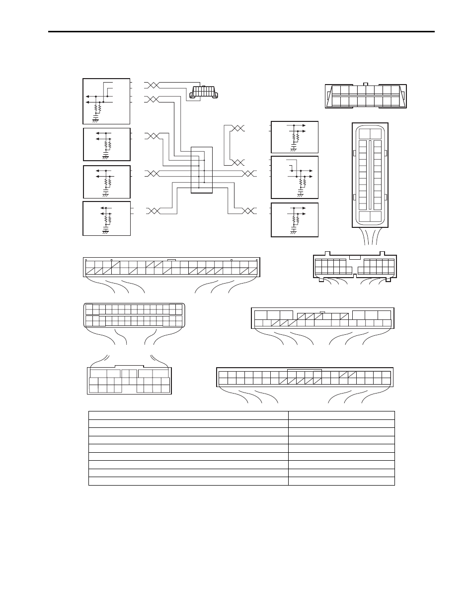
Wiring Diagram
WHT
RED
WHT
RED
G44-18
G44-19
G44
[A]
[B]
[C]
[H]
[G]
1
2
3
4
5
6
7
8
9
10
11
14
15
16
36
34 33 32
30 29
24 23
37
18
19
20
G28-8
G28-10
WHT/BLU
WHT/BLU
WHT/RED
WHT/RED E23-4
E23-19
WHT
RED E03-12
E03-10
E03-6
E03-8
WHT
RED
E92-17
E92-7
WHT
RED
E91-22
E91-23
WHT
RED
RED
G31-1
G31-3
G31-4
6
5
16 15 14 13 12 11
4 3
24 23
21
22
10 9
8
7
2
1
19
20
18 17
E92
2 1
E23
3
4
18
19
5
6
7
10
11
17
20
47 46
49
50
51
21
22
52
16
25
9
24
14
29
55
57
5453
59
60
58
26
27
28
15
30
56
48
32 31
34
35
36
37
40
42
3938
44
45
43
41
33
12
13
23
8
1
2
3
4
5
6
7
8
9
10
11
17
1615141312
2221201918
G28
[F]
G31
E91
1
2
3
4
7
8
9
10
11
14
15
16
36
34
35
24 23
21
22
28 27
25
26
37
39 38
40
18 17
13 12
19
20
1
2
3
10
11
12
16
17
18
15 14 13
19
20
21
25
26
5
6
[E]
[D]
E03
15
16
17
18
19
20
21
22
23
24
25
2
3
4
5
6
7
8
9
10
11
12
1
13
14
26
8 7 6 5 4 3 2 1
9
10
11
12
13
14
15
16
G31-2
WHT
1
2
3
4
9
5
6
7
8
I5JB0AA50017-03
[A]: Keyless start control module connector (viewed from harness side)
1. Keyless start control module
[B]: ECM connector (viewed from harness side)
2. TCM (A/T model)
[C]: TCM connector (viewed from harness side)
3. 4WD control module (if equipped)
[D]: DLC (viewed from harness side)
4. BCM
[E]: ABS hydraulic unit/control module connector (viewed from harness side)
5. DLC
[F]: Combination meter connector (viewed from harness side)
6. ECM
[G]: 4WD control module connector (viewed from harness side)
7. ABS hydraulic unit/control module
[H]: BCM connector (viewed from harness side)
8. Combination meter
9. Junction connector

10B-28 Body Electrical Control System:
DTC Detecting Condition and Trouble Area
DTC Confirmation Procedure
1) Clear DTC referring to “DTC Clearance”.
2) Start engine and run it for 1 min. or more.
3) Check DTC referring to “DTC Check”.
Troubleshooting
DTC detecting condition
Trouble area
BCM can not receive data sent by CAN from keyless start
control module for longer than specified time continuously.
• CAN communication circuit
• Keyless start control module
• BCM
Step
Action
Yes
No
1
Check DTC in BCM
Is DTC U1144 (No. 1144) and DTC U1073 (No. 1073)
detected together?
Go to “DTC U1073 (No.
1073): Control Module
Communication Bus
Off”.
Go to Step 2.
2
Check each control module connectors
1) Check connection of connectors of all control modules
communicating by means of CAN.
2) Recheck BCM for DTC.
Is DTC U1144 (No. 1144) detected?
Go to Step 3.
Intermittent trouble.
Check for intermittent
referring to “Intermittent
and Poor Connection
Inspection in Section
00”.
3
CAN communication circuit check
1) Turn ignition switch to OFF position.
2) Disconnect connectors of BCM and keyless start control
module communicating by means of CAN.
3) Check CAN communication circuit between control
modules for open, short and high resistance.
Is each CAN communication circuit in good condition?
Go to Step 4.
Repair circuit.
4
DTC Check
1) Turn ignition switch to OFF position.
2) Connect connectors to BCM and keyless start control
module.
3) Check DTC for ECM.
Is DTC P1618 detected by ECM?
Substitute a known-
good BCM and recheck.
Check keyless start
control module power
and ground circuit. If
circuit is OK, substitute
a known-good keyless
start control module and
recheck.
Body Electrical Control System: 10B-29
Inspection of BCM and its Circuits
S5JB0AA204017
BCM and its circuits can be checked at BCM wiring couplers by measuring voltage and resistance.
CAUTION
!
BCM cannot be checked by itself. It is strictly prohibited to connect voltmeter or ohmmeter to BCM
with couplers disconnected from it.
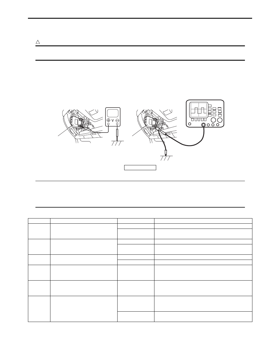
Voltage Check
1) Disconnect negative cable (–) at battery.
2) Remove steering column hole cover from instrument panel.
3) Check voltage at each terminal number of couplers connected.
For connector and terminal number, refer to “Connector Layout Diagram of BCM”.
NOTE
• As each terminal voltage is affected by the battery voltage, confirm that it is 11 V or more when
ignition switch is ON.
• Voltage with asterisk (*) can not be measured by voltmeter because it is pulse signal.
Check it with oscilloscope if necessary.
BCM connector “G30”
1
1
I5JB0AA20012-01
1. BCM
Terminal
Circuit
Normal voltage
Condition
G30-1
Power source (IG)
10 – 14 V
Ignition switch is at ON position
0 V
Ignition switch is at any position other than ON
position
G30-2
Power source (ACC)
10 – 14 V
Ignition switch is at ACC or ON position
0 V
Ignition switch is at any position other than ACC or
ON position
G30-3
Key reminder switch
10 – 14 V
Ignition key is inserted to ignition key cylinder
0 V
Ignition key is pulled out from ignition key cylinder
G30-4
Serial communication line for
HVAC control module
*0 – 1 V
↑↓
10 – 14 V
Refer to “Reference waveform No. 1: ”
G30-5
Serial communication line for
information display and HVAC
control module
*0 – 1V
↑↓
10 – 14 V
Refer to “Reference waveform No. 2: ”
G30-6
Rear wiper switch
*0 – 1 V
↑↓
10 – 14 V
Refer to “Reference waveform No. 3: ”
0 V
Ignition switch is at ON position and rear wiper
switch is at ON position
Нет комментариевНе стесняйтесь поделиться с нами вашим ценным мнением.
Текст