Suzuki Grand Vitara JB416 / JB420. Manual — part 85
1D-8 Engine Mechanical: For M16A Engine with VVT
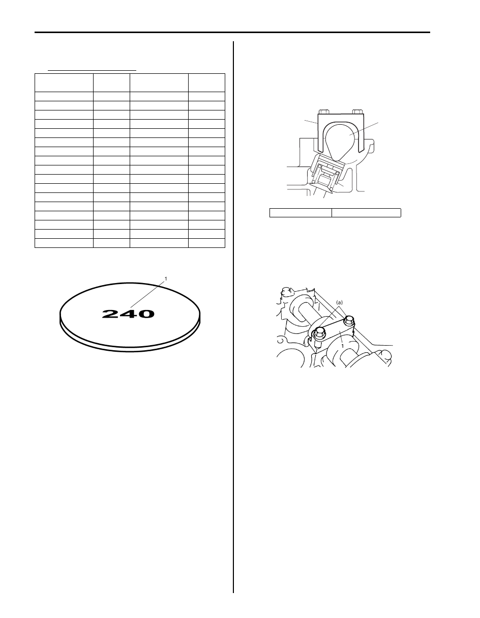
6) Select new shim No. (1) with a thickness as close as
possible to calculated value.
Available new shims No.
7) Install new shim facing shim No. side with tappet.
8) Lift valve by turning crankshaft counterclockwise (in
opposite direction against above Step 4)) and
remove special tool.
Special tool
(A): 09916–67020
(A): 09916–67021
9) Install camshaft housing (1) and tighten bolts to
specified torque.
Tightening torque
Camshaft housing bolt (a): 11 N·m (1.1 kgf-m,
8.0 lb-ft)
10) Check valve clearance again after adjusting it.
11) After checking and adjusting all valves.
12) Install cylinder head cover referring to “Cylinder
Head Cover Removal and Installation: For M16A
Engine with VVT”.
Thickness mm
(in.)
Shim No.
Thickness mm
(in.)
Shim No.
2.175 (0.0856)
218
2.600 (0.1024)
260
2.200 (0.0866)
220
2.625 (0.1033)
263
2.225 (0.0876)
223
2.650 (0.1043)
265
2.250 (0.0886)
225
2.675 (0.1053)
268
2.275 (0.0896)
228
2.700 (0.1063)
270
2.300 (0.0906)
230
2.725 (0.1073)
273
2.325 (0.0915)
233
2.750 (0.1083)
275
2.350 (0.0925)
235
2.775 (0.1093)
278
2.375 (0.0935)
238
2.800 (0.1102)
280
2.400 (0.0945)
240
2.825 (0.1112)
283
2.425 (0.0955)
243
2.850 (0.1122)
285
2.450 (0.0965)
245
2.875 (0.1132)
288
2.475 (0.0974)
248
2.900 (0.1142)
290
2.500 (0.0984)
250
2.925 (0.1152)
293
2.525 (0.0994)
253
2.950 (0.1161)
295
2.550 (0.1004)
255
2.975 (0.1171)
298
2.575 (0.1014)
258
3.000 (0.1181)
300
I2RH0B140015-01
1. Tappet
2. Camshaft
(A)
2
1
I3RM0A140006-01
I2RH0B140149-01
Engine Mechanical: For M16A Engine with VVT 1D-9
Repair Instructions
Air Cleaner Filter Removal and Installation
S5JB0A1416001
Removal
1) Open air cleaner case (1) by unhooking its clamps
(2).
2) Remove air cleaner filter from case.
Installation
Reverse removal procedure for installation.
Air Cleaner Filter Inspection and Cleaning
S5JB0A1416002
Inspection
Check air cleaner filter for dirt. Replace excessive dirty
filter.
Cleaning
Blow off dust by compressed air from air outlet side of
element.
Cylinder Head Cover Removal and Installation
S5JB0A1416011
Removal
1) Disconnect negative cable at battery.
2) Disconnect MAF sensor coupler (1).
3) Remove air cleaner case (2).
4) Remove cylinder head upper cover.
5) Disconnect ignition coil couplers (1).
6) Remove ignition coil assemblies (2) with high-
tension cord (3).
7) Remove wire harness clamp from cylinder head
cover.
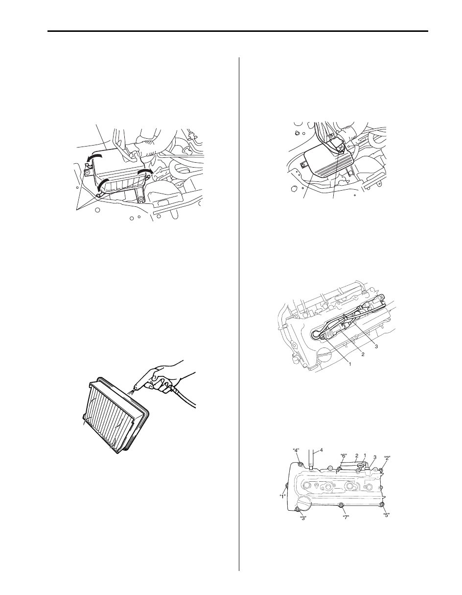
8) Remove oil level gauge (1).
9) Disconnect PCV hose (2) from PCV valve (3) and
disconnect breather hose (4) from cylinder head
cover.
10) Remove cylinder head cover mounting bolts in such
order as indicated in the figure.
1
2
I5JB0A141003-02
I2RH0B140150-01
2
1
I5JB0A141004-02
I2RH0B140032-01
I5JB0A141006-01
1D-10 Engine Mechanical: For M16A Engine with VVT
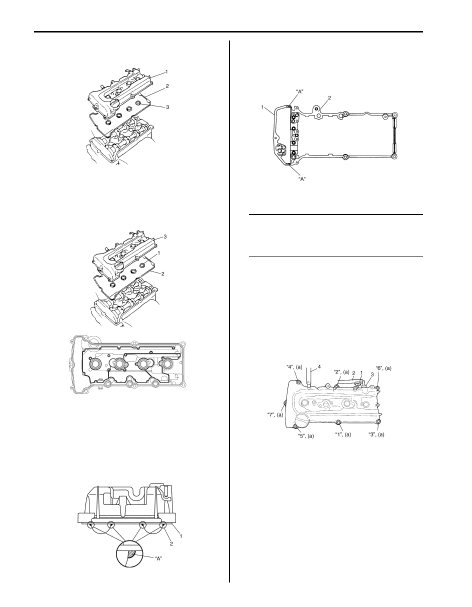
11) Remove cylinder head cover (1) with cylinder head
cover gasket (2) and spark plug hole gasket (3).
Installation
1) Install new spark plug hole gaskets (1) and new
cylinder head cover gasket (2) to cylinder head cover
(3) as shown in the figure.
2) Remove oil, old sealant, and dust from sealing
surfaces on cylinder head and cover. After cleaning,
apply sealant “A” to the following point.
• Cylinder head cover gasket (1) sealing surface
area (2) as shown.
“A”: Water tight sealant 99000–31250
(SUZUKI Bond No.1207F)
• Timing chain cover (1) and cylinder head (2)
mating surface as shown.
“A”: Water tight sealant 99000–31250
(SUZUKI Bond No.1207F)
3) Install cylinder head cover to cylinder head.
NOTE
When installing cylinder head cover, use care
so that cylinder head cover gasket or spark
plug hole gaskets will not get out of place or
fall off.
4) Tightening bolts in such order as indicated in the
figure a little at a time till they are tightened to
specified torque.
Tightening torque
Cylinder head cover bolt (a): 8 N·m (0.8 kgf-m,
6.0 lb-ft)
5) Connect PCV hose (2) to PCV valve (3).
6) Connect breather hose (4).
7) Install oil level gauge (1).
8) Install wire harness clamp to cylinder head cover.
9) Install ignition coil assemblies with high-tension cord.
10) Connect ignition coil couplers and clamp harness
securely.
11) Install cylinder head upper cover.
12) Connect negative cable at battery.
I5RS0D140014-01
I5RS0D140015-01
I2RH0B140036-01
I2RH0B140037-01
I5JB0A141007-01
Engine Mechanical: For M16A Engine with VVT 1D-11
Throttle Body and Intake Manifold Components
S5JB0A1416009
Throttle Body On-Vehicle Inspection
S5JB0A1416005
Check electric throttle body assembly referring to “Throttle Valve Operation Check” and “Electric Throttle Body
Assembly Operation Check” under “Electric Throttle Body Assembly On-Vehicle Inspection in Section 1C”.
I5JB0A141005-05
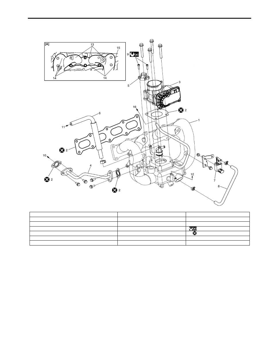
[A]: Installing location of intake manifold bolt and nut
7. EVAP canister purge valve
14. Intake manifold bolt (short)
1. Intake manifold
8. EVAP canister purge valve hose
15. Intake manifold bolt (long)
2. Gasket
9. MAP sensor bolt
16. To delivery pipe
3. Electrical throttle body
10. To EGR valve
: 5 N
⋅m (0.5 kgf-m, 4.0 lb-ft)
4. EGR pipe
11. To PCV valve
: Do not reuse.
5. MAP sensor
12. To brake booster
6. PCV hose
13. Intake manifold nut
Нет комментариевНе стесняйтесь поделиться с нами вашим ценным мнением.
Текст