Suzuki Grand Vitara JB416 / JB420. Manual — part 86

1D-12 Engine Mechanical: For M16A Engine with VVT
Electric Throttle Body Assembly Removal and
Installation
S5JB0A1416045
Removal
1) Disconnect negative cable at battery.
2) Drain coolant referring to “Cooling System Draining
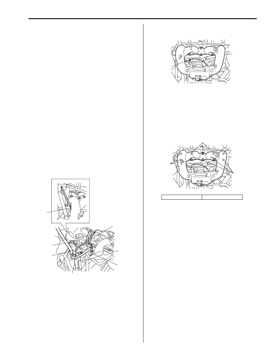
3) Detach breather union (1) from air intake pipe (2).
4) Disconnect air intake pipe (2).
5) Disconnect engine coolant hoses (1) from electric
throttle body assembly (3).
6) Disconnect connector (2) from electric throttle body
assembly.
7) Remove electric throttle body assembly from intake
manifold.
Installation
1) Clean mating surfaces and install new throttle body
gasket to intake manifold.
2) Install electric throttle body assembly (1) to intake
manifold.
3) Connect connector (2) to electric throttle body
assembly securely.
4) Connect engine coolant hoses (3) to electric throttle
body assembly (1).
5) Connect air intake pipe (1) and breather union (2).
6) Tighten air intake pipe bolt (3) to specified torque.
Tightening torque
Air intake pipe bolt (a): 3 N·m (0.3 kgf-m, 2.5 lb-
ft)
7) Refill coolant referring to “Cooling System Flush and
8) Connect negative cable at battery.
9) Perform calibration of electric throttle body assembly
referring to “Electric Throttle Body System
Calibration in Section 1C” if replaced.
Throttle Body Cleaning
S5JB0A1416046
Clean electric throttle body assembly referring to
“Throttle Valve Visual Check” under “Electric Throttle
Body Assembly On-Vehicle Inspection in Section 1C”.
1
2
I5JB0A141008-03
3
2
1
I5JB0A141009-02
1
2
3
I5JB0A141010-02
2
1
3, (a)
I5JB0A141011-03
Engine Mechanical: For M16A Engine with VVT 1D-13
Intake Manifold Removal and Installation
S5JB0A1416010
Removal
1) Relieve fuel pressure in fuel feed line referring to
“Fuel Pressure Relief Procedure in Section 1G”.
2) Remove throttle body referring to “Electric Throttle
Body Assembly Removal and Installation: For M16A
Engine with VVT”.
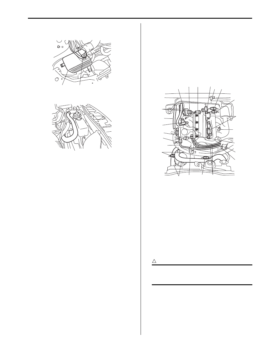
3) Disconnect the following hoses:
• Brake booster hose (2) from intake manifold
• PCV hose (3) from intake manifold
• EVAP canister purge hose (4) from intake
manifold
• Vacuum hose (5) from intake manifold
• Water No.1 hose (9) from intake manifold
• Water No.2 hose (10) from intake manifold
4) Disconnect the following electric wires:
• Injectors
• Ground terminal (6) from intake manifold
• MAP sensor (1)
5) Remove EVAP canister purge valve (7).
6) Remove intake manifold bracket (8).
7) Remove delivery pipe referring to “Fuel Injector
Removal and Installation in Section 1G”.
8) Remove intake manifold (1) and EGR pipe bolt (2)
from cylinder head, and then remove its gaskets.
Installation
Reverse removal procedure for installation noting the
followings.
• Use new intake manifold gasket.
• Use new EGR pipe gasket.
• Install intake manifold bolt and nut (1) as shown in
figure.
• Check to ensure that all removed parts are back in
place.
• Refill cooling system referring to “Cooling System
Flush and Refill in Section 1F”.
• Upon completion of installation, turn ignition switch
ON but engine OFF and check for fuel leaks.
• Finally, start engine and check for engine coolant
leaks.
6
1
2
5
8
4
7
10
3
9
I5JB0A141012-04
2. Short bolt
3. Long bolt
1
2
I5JB0A141013-02
2
1
2
3
I5JB0A141014-02
1D-14 Engine Mechanical: For M16A Engine with VVT
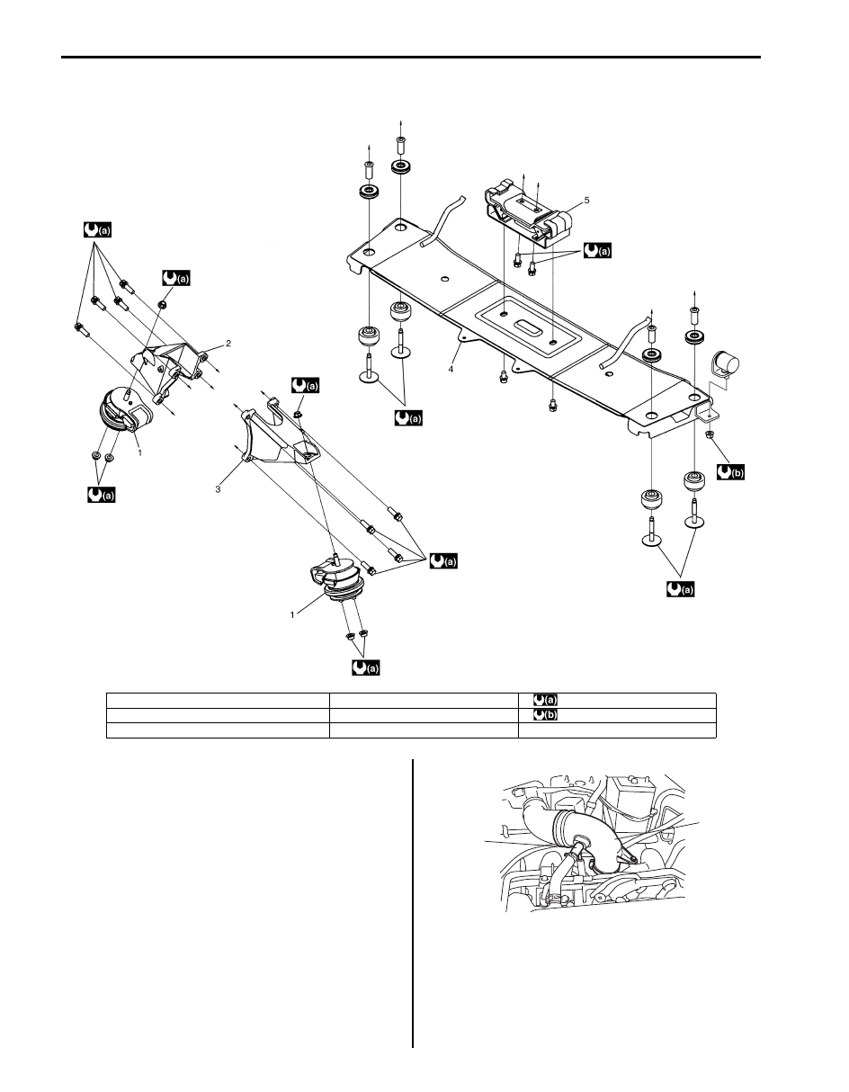
Engine Mountings Components
S5JB0A1416012
Engine Assembly Removal and Installation
S5JB0A1416013
Removal
1) Relieve fuel pressure according to “Fuel Pressure
Relief Procedure in Section 1G”.
2) Disconnect negative cable at battery.
3) Drain engine oil referring to “Engine Oil and Filter
4) Drain coolant referring to “Cooling System Draining
5) Disconnect breather hose (1) from air intake pipe (2).
6) Remove air intake pipe (2).
I5JB0A141015-02
1. Engine front mounting
4. Engine rear mounting member
: 55 N
⋅m (5.5 kgf-m, 40.0 lb-ft)
2. Engine front mounting right bracket
5. Engine rear mounting
: 17 N
⋅m (1.7 kgf-m, 12.5 lb-ft)
3. Engine front mounting left bracket
6. Engine mounting nut
1
2
I5JB0A141008-03
Engine Mechanical: For M16A Engine with VVT 1D-15
7) Disconnect MAF sensor connector (1).
8) Remove air cleaner case (2).
9) Disconnect radiator inlet hose (1).
10) Remove P/S pump belt referring to “P/S Pump and
11) Disconnect the following electric wires:
• MAP sensor (1)
• ECT sensor (2)
• EGR valve (3)
• CMP sensor (4)
• EVAP canister purge valve (5)
• Ignition coil assembly (6)
• Injectors (7)
• A/F sensor (8)
• HO2S (9)
• Engine oil pressure switch (10)
• CKP sensor (11)
• Back-up light switch (12)
• Generator (13)
• Starting motor
• Ground terminal from intake manifold (14)
• Magnet clutch switch of A/C compressor (15) (if
equipped)
• P/S pump (16) (if equipped)
• Electric throttle body (17)
• Oil control valve (18)
• Transfer actuator (19)
• Differential lock switch (20)
• 4H switch (21)
• Each wire harness clamps
12) Disconnect the following hoses:
• Brake booster hose (22) from intake manifold
• Radiator inlet and outlet hoses (26) from each
pipe
• Heater inlet and outlet hoses (23) from each pipe
• Fuel hoses (24) from fuel pipes
• EVAP canister purge (25) hose from purge valve
• Clutch oil pipe from transmission housing
13) Remove shift control lever referring to “Transmission
Shift Control Lever Removal and Installation in
Section 5B”.
14) Remove exhaust No.1, No.2 and center pipes
referring to “Exhaust System Components in Section
1K”.
15) Remove front and rear propeller shafts referring to
“Propeller Shaft Removal and Installation in Section
3D”.
16) With hose connected, detach P/S pump from its
bracket (if equipped) referring to “P/S Pump
Removal and Installation for M16 Engine Model in
Section 6C”.
CAUTION
!
Suspend removed P/S pump at a place where
no damage will be caused during removal
and installation of engine assembly.
2
1
I5JB0A141004-02
1
I5JB0A141016-02
1
2
3
4
5
6
7
8
9
10
11
12
13
14
15
16
17
18
19
20
23
22
21
I5JB0A141027-01
Нет комментариевНе стесняйтесь поделиться с нами вашим ценным мнением.
Текст