Suzuki Grand Vitara JB416 / JB420. Manual — part 140

1K-2 Exhaust System:
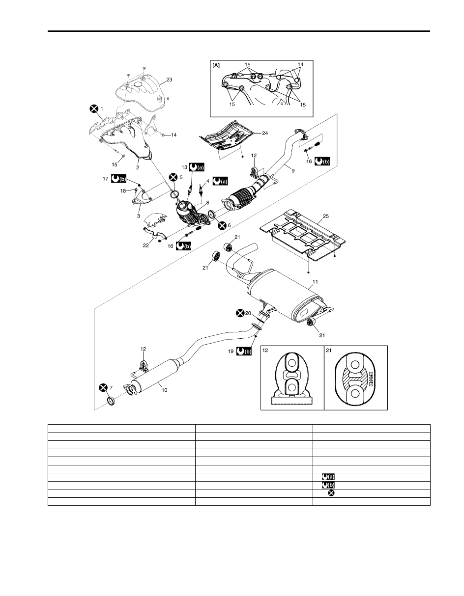
For M16 Engine Model
I5JB0A1B1002-03
[A]: Installing location of exhaust manifold bold and nut.
9. Exhaust pipe No.2
18. Exhaust pipe No.1 bracket bolt
1. Exhaust manifold gasket
10. Exhaust center pipe
19. Exhaust center pipe nut
2. Exhaust manifold
11. Muffler
20. Exhaust center pipe gasket
3. Exhaust pipe No.1 bracket
12. Mounting
: 45 N
⋅m (4.5 kgf-m, 32.5 lb-ft)
4. HO2S
13. A/F sensor
: 50 N
⋅m (5.0 kgf-m, 36.5 lb-ft)
5. Exhaust pipe No.1 gasket
14. Exhaust manifold bolt
: 43 N
⋅m (4.3 kgf-m, 31.0 lb-ft)
6. No.1 seal ring
15. Exhaust manifold nut
: Do not reuse.
7. No.2 seal ring
16. Exhaust pipe bolt
8. Exhaust pipe No.1
17. Exhaust pipe No.1 bracket nut
Exhaust System: 1K-3
For J20 Engine Model
I5JB0A1B1003-05
[A]: Installing location of exhaust manifold bold and nut.
10. Exhaust center pipe
20. Exhaust center pipe gasket
1. Exhaust manifold gasket
11. Muffler
21. Muffler mounting
2. Exhaust manifold
12. Mounting
22. Exhaust pipe No.2 bracket
3. Exhaust pipe No.1 bracket
13. A/F sensor
23. Exhaust manifold cover
4. HO2S
14. Exhaust manifold bolt
24. Heat protector panel
5. Exhaust pipe No.1 gasket
15. Exhaust manifold nut
25. Heat protector rear panel
6. No.1 seal ring
16. Exhaust pipe bolt
: 45 N
⋅m (4.5 kgf-m, 32.5 lb-ft)
7. No.2 seal ring
17. Exhaust pipe No.1 bracket nut
: 50 N
⋅m (5.0 kgf-m, 36.5 lb-ft)
8. Exhaust pipe No.1
18. Exhaust pipe No.1 bracket bolt
: Do not reuse.
9. Exhaust pipe No.2
19. Exhaust center pipe nut

1K-4 Exhaust System:
Exhaust Manifold Removal and Installation (For
M16 Engine Model)
S5JB0A1B06003
Removal
WARNING
!
To avoid danger of being burned, do not
service exhaust system while it is still hot.
Service should be performed after system
cools down.
1) Disconnect negative cable at battery.
2) Remove exhaust pipe No.1 bracket.
3) Remove exhaust manifold (1) and its gasket from
cylinder head.
Installation
1) Install new gasket to cylinder head and exhaust pipe
No.1. Then install exhaust manifold.
Tighten manifold bolts (1) and nuts (2) to specified
torque.
Tightening torque
Exhaust manifold bolt and nut (a): 50 N·m (5.0
kgf-m, 36.5 lb-ft)
NOTE
Be sure to install exhaust manifold bolts and
nuts to proper location referring to “Exhaust
System Components”.
2) Install exhaust pipe No.1 bracket (1).
Tightening torque
Exhaust pipe No.1 bracket bolt and nut (a): 50
N·m (5.0 kgf-m, 36.5 lb-ft)
3) Connect negative cable at battery.
4) Check exhaust system for exhaust gas leakage.
Exhaust Manifold Removal and Installation (For
J20 Engine Model)
S5JB0A1B06005
Removal
WARNING
!
To avoid danger of being burned, do not
service exhaust system while it is still hot.
Service should be performed after system
cools down.
1) Relieve fuel pressure in fuel feed line according to
“Fuel Pressure Relief Procedure in Section 1G”.
2) Disconnect negative cable at battery.
3) Drain coolant referring to “Cooling System Draining
4) Disconnect fuel hoses (2) from fuel pipes (1).
5) Disconnect water outlet pipe (3) from radiator inlet
hose.
6) Remove exhaust manifold cover (4).
1
I5JB0A1B1004-01
2, (a)
1, (a)
I5JB0A1B1001-01
I5JB0A1B1009-01
3
2
1
4
2
I5JB0A1B1005-01

Exhaust System: 1K-5
7) Remove exhaust pipe No.1 bracket (1).
8) Remove exhaust manifold (2) and its gasket (3) from
cylinder head.
Installation
1) Install new gasket (1) to cylinder head and exhaust
pipe No.1. Then install exhaust manifold (2).
Tighten manifold bolts (4) and nuts (5) to specified
torque.
Tightening torque
Exhaust manifold bolt and nut (b): 50 N·m (5.0
kgf-m, 36.5 lb-ft)
NOTE
Be sure to install exhaust manifold bolts and
nuts to proper location referring to “Exhaust
System Components”.
2) Install exhaust pipe No.1 bracket (3) to exhaust
manifold.
Tighten nuts to specified torque.
Tightening torque
Exhaust No.1 pipe nut (a): 50 N·m (5.0 kgf-m,
36.5 lb-ft)
3) Install exhaust manifold cover (1).
4) Connect water outlet pipe (2) from radiator inlet
hose.
5) Connect fuel pipe (3) from fuel hoses.
6) Refill cooling system referring to “Cooling System
Flush and Refill in Section 1F”.
7) Connect negative cable at battery.
8) Verify that there is no fuel leakage, coolant leakage
and exhaust gas leakage at each connection.
Exhaust Pipe and Muffler Removal and
Installation
S5JB0A1B06004
For replacement of exhaust pipe, be sure to hoist vehicle
and observe WARNING under “Exhaust System
Components” and the following.
WARNING
!
To avoid danger of being burned, do not
service exhaust system while it is still hot.
Service should be performed after system
cools down.
CAUTION
!
Exhaust manifold have three way catalytic
converter in it, it should not be exposed to
any impulse.
Be careful not to drop it or hit it against
something.
• Tighten bolts and nuts to specified torque when
reassembling. Refer to “Exhaust System
Components”.
• After installation, start engine and check each joint of
exhaust system for leakage.
I5JB0A1B1006-01
I5JB0A1B1007-04
3
2
1
I5JB0A1B1008-01
Нет комментариевНе стесняйтесь поделиться с нами вашим ценным мнением.
Текст