Suzuki Grand Vitara JB416 / JB420. Manual — part 139
1J-14 Charging System:
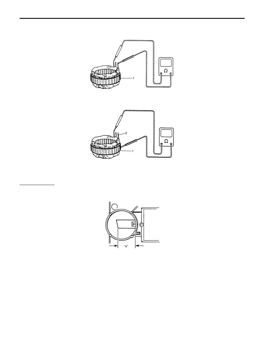
Stator
• Using ohmmeter, check all leads for continuity. If there is no continuity, replace stator (1).
• Using ohmmeter, check that there is no continuity between coil leads (2) and stator core (1). If there is continuity,
replace stator.
Brush and brush holder
Check each brush for wear by measuring its length. If brush is found worn down to service limit, replace brush.
Brush length “a”
Standard: 16 mm (0.63 in.)
Limit: 5 mm (0.20 in.)
IYSQ011A0037-01
IYSQ011A0038-01
IYSQ011A0039-01

Charging System: 1J-15
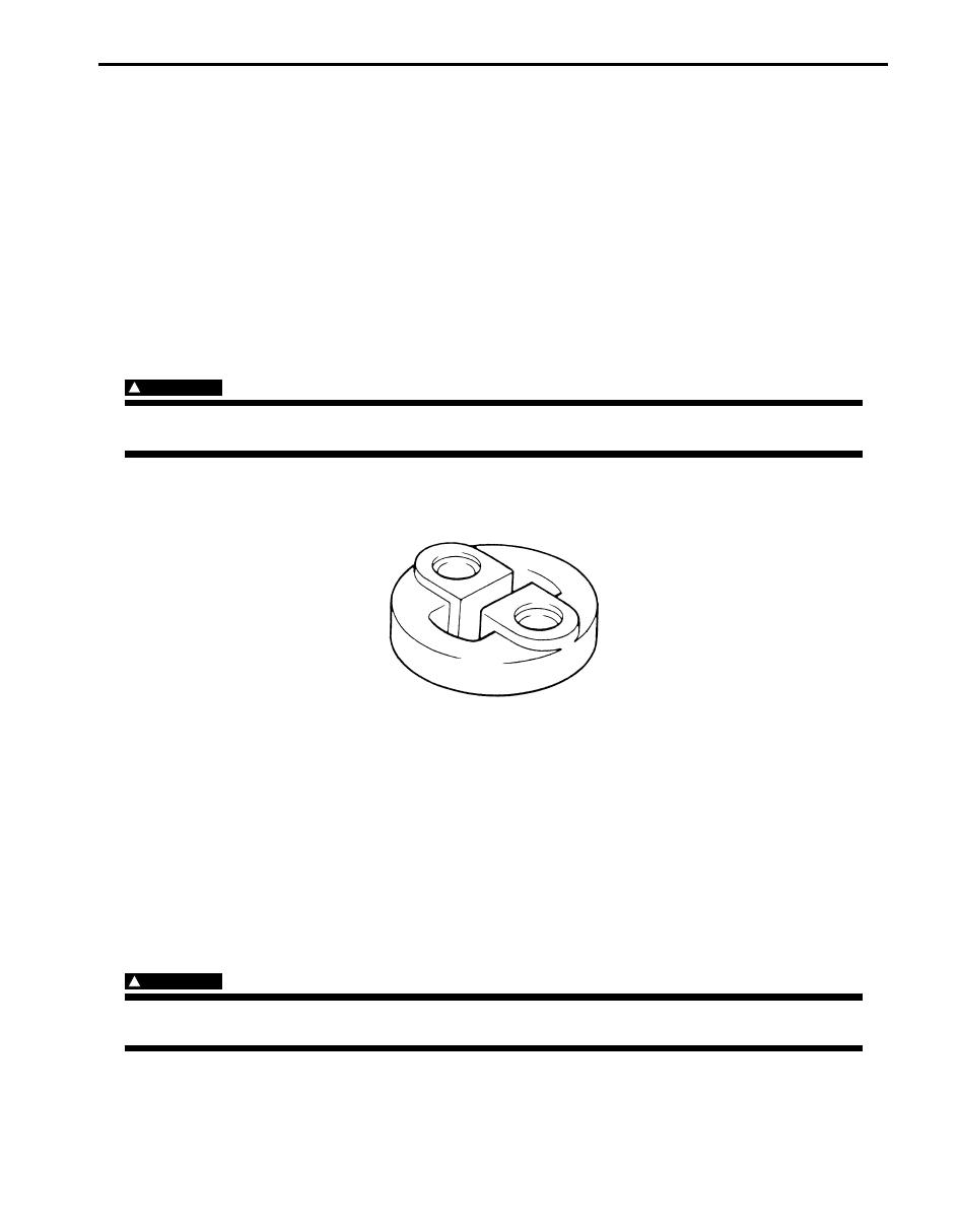
Rectifier
1) Using ohmmeter, check continuity between each of upper and lower rectifier bodies and each diode lead (2).
Check both directions by reversing probes of ohmmeter and there should be only one-way continuity in each case.
If check result is not satisfactory, replace rectifier (1).
2) In the same manner as described in above Step 1), check that there is only one-way continuity between both leads
of diode trio.
Condenser
Check condenser capacity.
Condenser capacity
0.5
µF
IYSQ011A0040-01
1. Rectifier
2. Condenser
IYSQ011A0041-01

1J-16 Charging System:
Specifications
Charging System Specifications
S5JB0A1A07001
Battery
Battery
: CCA 180A (28 AH/5 H) 12V or CCA 210A (36 AH/5 H) 12V
NOTE
The battery used in each vehicle is one of the following two types, depending on specification.
Generator
NOTE
The generator used in each vehicle is one of the following three types, depending on specification.
Tightening Torque Specifications
S5JB0A1A07002
NOTE
The specified tightening torque is also described in the following.
“Generator Dismounting and Remounting”
“Generator Components”
Reference:
For the tightening torque of fastener not specified in this section, refer to “Fastener Information in Section 0A”.
Battery type
55B24R (S)
55D23L
Rated Capacity
AH/5HR, 12 Volts
36
48
Electrolyte
L (US/Imp. pt)
3.1
(6.55/5.46)
3.9
(8.24/6.86)
Electrolyte S.G.
1.28 when fully charged at 20
°C (68 °F)
Type
80 A type
Rated voltage
12 V
Nominal output
80 A
Permissible max. speed
18000 r/min (rpm)
No-load speed
1200 r/min (rpm)
Setting voltage
14.2 to 14.8 V
Permissible ambient
temperature
–30 to 100
°C (–22 to 212 °F)
Polarity
Negative ground
Rotation
Clockwise viewed from pulley side
Fastening part
Tightening torque
Note
N
⋅m
kgf-m
lb-ft
Generator adjusting bolt
25
2.5
18.5
Generator pivot bolt
52.5
5.25
38.0
Generator adjuster bolt
7.0
0.7
5.0
Exhaust System: 1K-1
Engine
Exhaust System
General Description
Exhaust System Description
S5JB0A1B01001
The exhaust system consists of an exhaust manifold, three-way catalytic converter (TWC) in catalyst case, exhaust
pipes, a muffler and seals, gasket and etc.
The three-way catalytic converter is an emission control device added to the exhaust system to lower the levels of
Hydrocarbon (HC), Carbon Monoxide (CO), and Oxides of Nitrogen (NOx) pollutants in the exhaust gas.
Diagnostic Information and Procedures
Exhaust System Check
S5JB0A1B04001
WARNING
!
To avoid the danger of being burned, do not touch the exhaust system when the system is hot. Any
service on the exhaust system should be performed when the system is cool.
At every interval of periodic maintenance service, and when vehicle is raised for other service, check exhaust system
as follows:
• Check rubber mountings for damage, deterioration, and out of position.
• Check exhaust system for leakage, loose connection, dent and damage.
• If bolts or nuts are loosened, tighten them to specified torque referring to “Exhaust System Components”.
• Check nearby body areas damaged, missing, or mispositioned part, open seam, hole connection or any other
defect which could permit exhaust fumes to seep into vehicle.
• Make sure that exhaust system components have enough clearance from underbody to avoid overheating and
possible damage to passenger compartment carpet.
• Any defect should be fixed at once.
Repair Instructions
Exhaust System Components
S5JB0A1B06001
WARNING
!
To avoid the danger of being burned, do not touch the exhaust system when the system is hot. Any
service on the exhaust system should be performed when the system is cool.
IYSY011B0003-01
Нет комментариевНе стесняйтесь поделиться с нами вашим ценным мнением.
Текст