BMW 3 (E46). Manual — part 137
WARNING!
Make sure that the car is firmly
supported on jack stands designed for
the purpose. Place the jack stands
beneath a structural chassis point. Do
not place jack stands under
suspension parts.
-
Remove splash shield under engine
compartment.
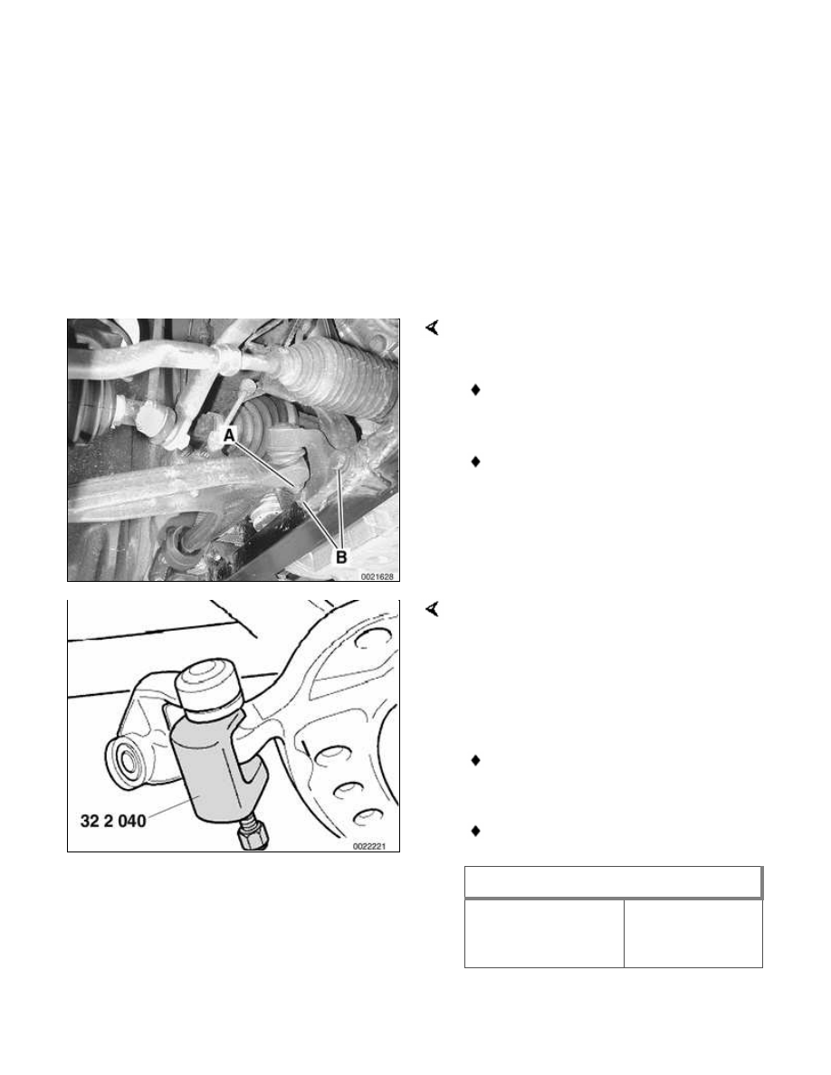
Remove inner ball joint fasteners from
control arm and subframe.
Remove nut (A) from ball joint
shaft.
Remove bolts (B) from subframe.
Use BMW special tool 32 2 040 or
equivalent to separate ball joint from
control arm.
-
Installation is reverse of removal,
noting the following:
Make sure thread bores, bolts, nuts
and mating surfaces are clean.
Use new self-locking nuts or bolts.
Tightening torques
Inner ball joint
mount to subframe
M12 bolt
77 Nm (57 ft-lb)
Tightening torques
Inner ball joint to
control arm M14
self-locking nut
(always replace)
80 Nm (59 ft-lb)
Control arm bushings, rear
wheel drive
CAUTION!
Never reuse a rubber bushing that
has been pulled off the control
arm. The rubber coated inner
sleeve is destroyed when it is
pulled off dry.
Check with an authorized BMW
parts dealer for the latest
information about control arm
bushing applications on E46 cars.
Control arm bushings should always be
replaced in pairs. The two bushings and
bushing carriers should have the same
markings, indicating same manufacturer.
-
To gain access to bushing, remove
control arm as described earlier.
-
Use puller to remove rear bracket
and bushing from control arm.
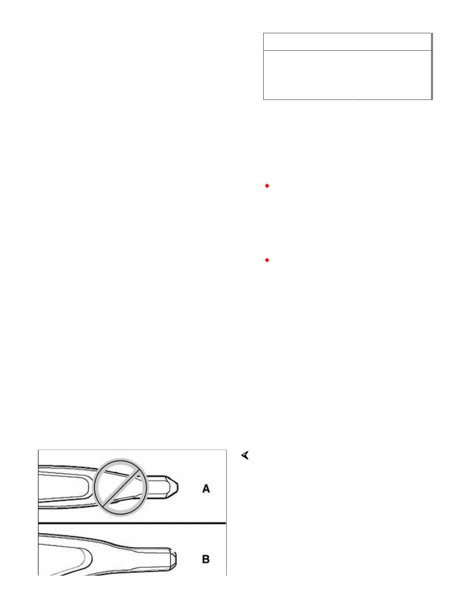
Inspect pin (rubber bushing) end of
control arm. Replace control arm with
end A.
Note:
Control arms with pin shape A have been
superseded by parts with pin shape B.
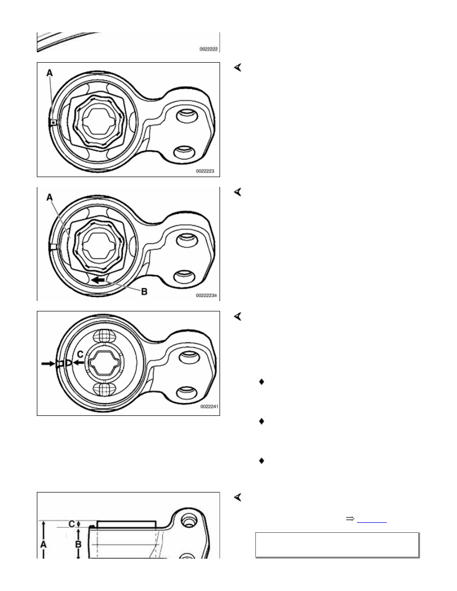
Inspect bushing bracket. Replace
bracket if there is a center punch mark at
boss A.
WARNING!
If a bushing bracket with the center
punch mark is reused with a new
bushing, the bushing may fall out.
Use press tools to remove old bushing
and press in new. Be sure to line up
marks on new bushing with boss on
bracket. Depending on manufacturer,
mark on bushing may consist of:
Extra buffer on inner part of
bushing (A)
Arrow on rubber webbing of
bushing (B)
Indent on outer casing of bushing
(C)
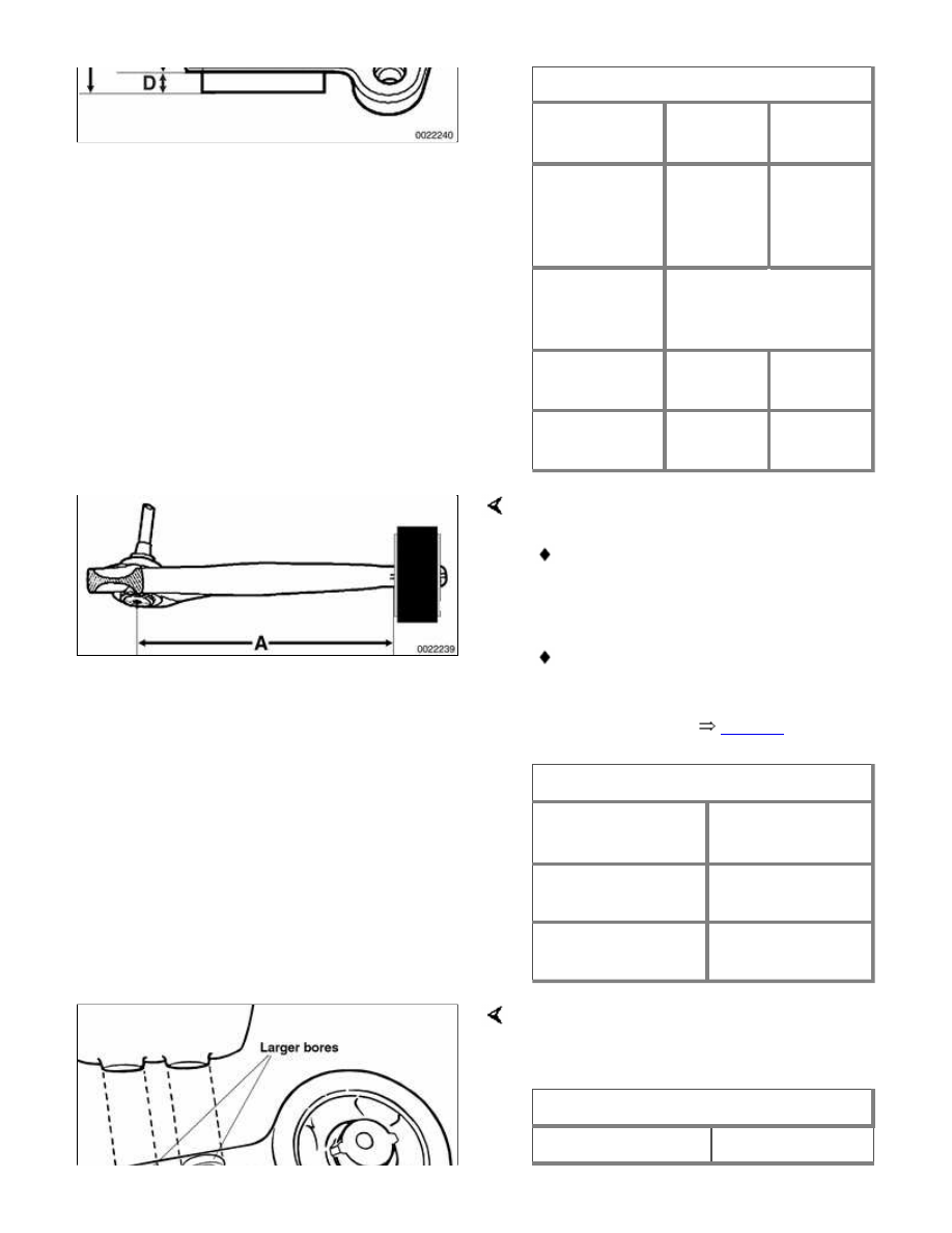
New bushing must be pressed in so that
it protrudes the correct distance from
edges of bracket. See
Table a
.
Table a. Control arm bushing
protrusion (rear wheel drive models)
Dimension
60 mm
bushing
66 mm
bushing
A = Total
bushing
length
(nominal)
50.5 mm
(1.99 in.)
53.5 mm
(2.11 in.)
B = Bracket
width
(nominal)
34.0 mm (1.36 in.)
C = Fixed
measurement
8.5 mm
(0.33 in.)
12.0 mm
(0.47 in.)
D =
Protrusion
8.0 mm
(0.31 in)
7.5 mm
(0.29 in.)
When installing bushing on control arm:
Use soapy water on control pin and
rubber bushing to facilitate
assembly.
Make sure dimension A(distance
from inner ball joint to edge of
control arm bushing) is correct after
assembly. See
Table b
.
Table b. rear wheel drive models)
Bushing diameter
or model
Bushing
distance A
60 mm
289 ± 1 mm
(11.38 ± 0.04 in.)
66 mm
290.9 ± 1 mm
(11.45 ± 0.04 in.)
Be sure to reinstall bushing bracket to
frame rail correctly, with larger centering
bores facing up toward body.
Tightening torque
Control arm rear
59 Nm (44 ft-lb)
Нет комментариевНе стесняйтесь поделиться с нами вашим ценным мнением.
Текст