Hummer H1 (1992-1998). Manual — part 55
Change 1 2-183
2 - 4 1 . ENGINE ASSEMBLY FROM SUBASSEMBLIES (Cont’d)
5.
Tighten all studs (6) and (7) and capscrews (8) and (9) to 30 lb-ft (41 N
•
m), following torque
sequence shown.
NOTE
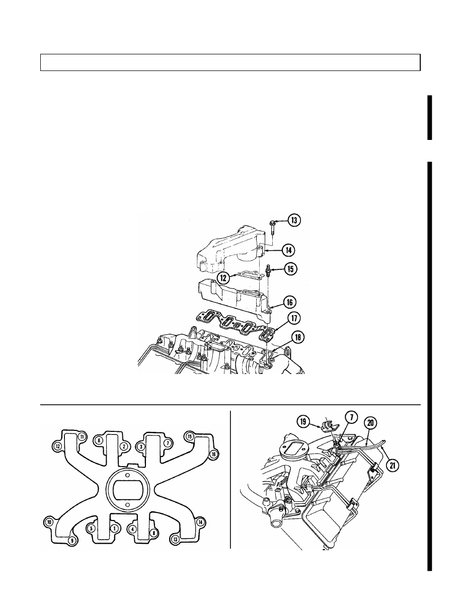
Perform steps 6 through 9 for turbocharged engines.
6.
Install gasket (17) and intake manifold (16) on cylinder head (18) with eight studs (15).
7.
Beginning at center of intake manifold (16) and working toward ends, tighten studs (15) to 30 lb-ft
(41 N
•
m).
8.
Repeat steps 6 and 7 for opposite side.
NOTE
Install turbocharger before installing center intake manifold.
9.
Install two gaskets (12) and center intake manifold (14) on intake manifolds (16) with six
capscrews (13). Tighten capscrews (13) to 17 lb-ft (23 N
•
m).
10.
Secure fuel supply line (21) and hose (20) to stud (7) with clamp (19).
TORQUE SEQUENCE
TURBOCHARGED ENGINE
2-184
Change 1
2 - 4 1 . ENGINE ASSEMBLY FROM SUBASSEMBLIES (Cont’d)
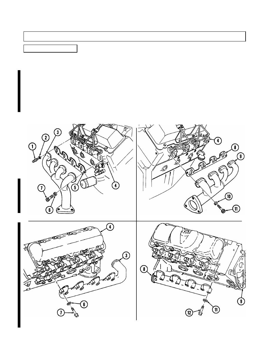
y. Exhaust Manifolds
LEFT EXHAUST MANIFOLD
TURBO LEFT EXHAUST MANIFOLD
TURBO RIGHT EXHAUST MANIFOLD
RIGHT EXHAUST MANIFOLD
NOT E
• Early production vehicles may have a socket-head screw in
place of stud.
• Turbo exhaust manifolds use hex-head capscrews and do not
have gaskets or stud as indicated in steps 1 through 3.
1 .
Install gasket (5) and left exhaust manifold (3) on cylinder head (4) with seven washers (6) and
socket-head screws (7). Using 8-mm hex-head driver, tighten socket-head screws (7) to 18-25 lb-ft
(24-34 N
•
m ) .
2.
Install washer (2) and stud (1) on left exhaust manifold (3) and cylinder head (4). Tighten stud (1) to
18-25 lb-ft (24-34 N
•
m).
3 .
Install gasket (8) and right exhaust manifold (9) on cylinder head (4) with eight washers (10) and socket-
head screws (11). Using 8-mm hex-head driver, tighten socket-head screws (11) to 18-25 lb-ft (24-34 N
•
m ) .
Change 1
2-184.1
2 - 4 1 . ENGINE ASSEMBLY FROM SUBASSEMBLIES (Cont’d)
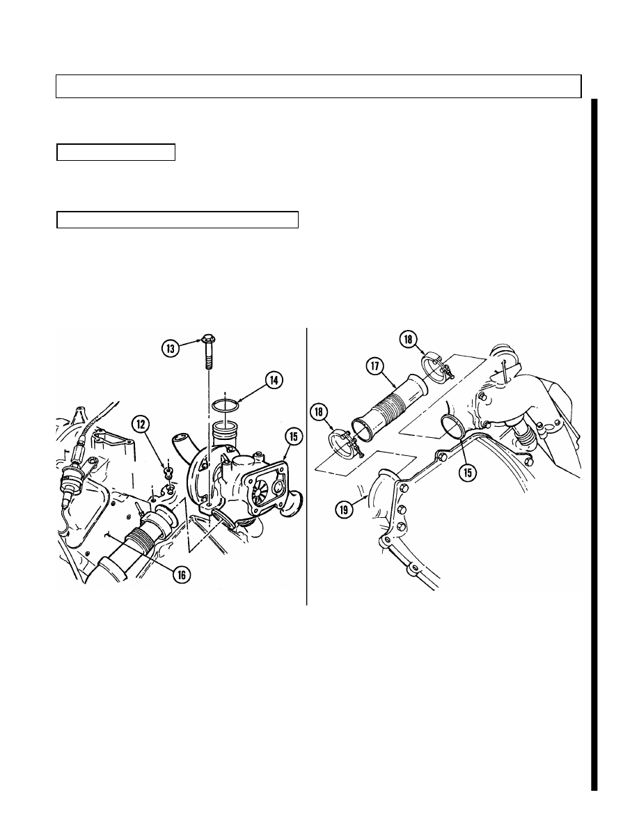
y.1.
Turbocharger
1.
Install turbocharger oil gasket (12) and turbocharger (15) on engine block (16) with two capscrews (13).
2 .
Install O-ring (14) on turbocharger (15) outlet.
y.2.
Manifold-to-Turbocharger Exhaust Pipe
1.
Install two clamps (18) on exhaust pipe (17).
2.
Install exhaust pipe (17) on turbocharger (15) and tighten clamp (18).
3.
Install exhaust pipe (17) on exhaust manifold (19) and tighten clamp (18).
4.
Repeat steps 1 through 3 for opposite side.
NOTE
Perform tasks y.1 through y.4 for 6.5L turbo engines only.
2-184.2
Change 1
2 - 4 1 . ENGINE ASSEMBLY FROM SUBASSEMBLIES (Cont’d)
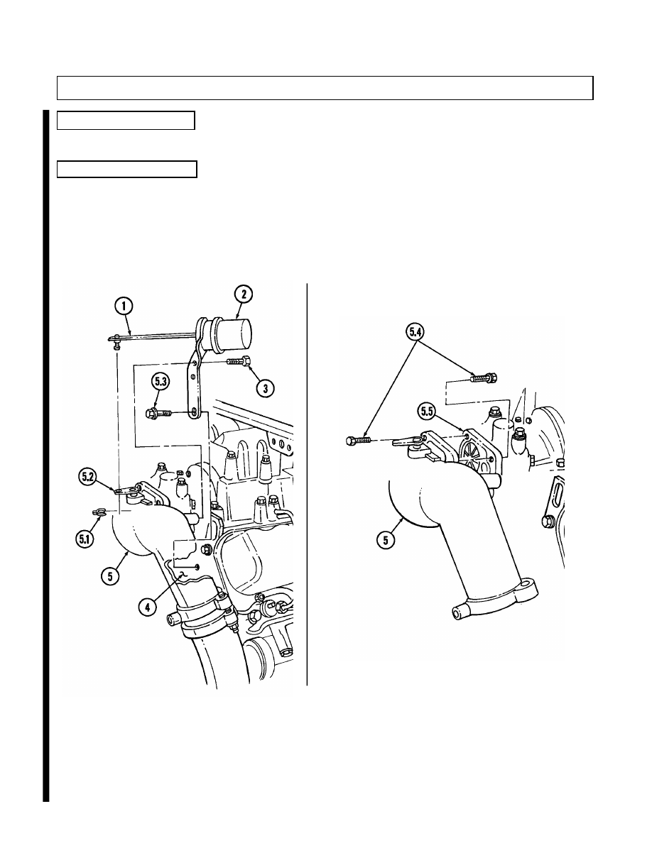
y.3. Wastegate Housing
Install wastegate housing (5) on turbocharger (5.5) with four capscrews (5.4).
y.4. Wastegate Actuator
1.
Install wastegate actuator (2) on cylinder head (4) with capscrew (5.3).
2.
Install wastegate actuator (2) on wastegate housing (5) with two capscrews (3).
3.
Install actuator rod (1) on wastegate bellcrank (5.2) with clip (5.1).
Нет комментариевНе стесняйтесь поделиться с нами вашим ценным мнением.
Текст