Hummer H1 (2002+). Manual — part 108
______________
Wheels and Tires/Central Tire Inflation System (CTIS) 6-47
®
05745159
DEFLATE VALVE ASSEMBLY REPLACEMENT
WARNING: CTIS components are subject to high air
pressure. Always relieve air pressure before loosening
or removing air system components by disconnecting
quick-disconnect valve assemblies. Failure to follow
this warning may result in serious injury.
Removal
1.
Raise and secure hood.
2.
Disconnect deflate valve electrical connector (Figure 6-65).
3.
Remove screws and deflate valve from manifold.
Cleaning and Inspection
Clean and inspect deflate valve and bracket. Check for cracks
and stripped threads. Replace if defective.
Installation
CAUTION: Do not allow sealant into air system. Sealant will
damage CTIS components.
NOTE: Apply sealant to threads prior to installation.
1.
Secure deflate valve to manifold with screws (Figure 6-65).
2.
Connect deflate valve electrical connector.
3.
Lower and secure hood.
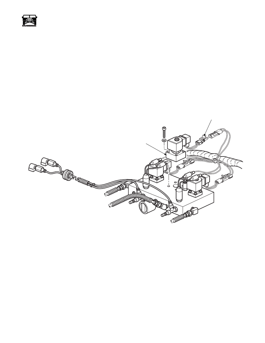
Figure 6-65: Deflate Valve Assembly Mounting
9-S06-003
ELECTRICAL
CONNECTOR
DEFLATE
VALVE

6-48
Wheels and Tires/Central Tire Inflation System (CTIS)
_______________
®
DUST EXCLUDER REPLACEMENT
WARNING: CTIS components are subject to high air
pressure. Always relieve air pressure before loosening
or removing air system components by disconnecting
quick-disconnect valve assemblies. Failure to follow
this warning may result in serious injury.
Removal
1.
Raise and secure hood.
2.
Remove dust excluder from manifold (Figure 6-66).
Cleaning and Inspection
Clean and inspect dust excluder. Check for cracks and stripped
threads. Replace if defective.
Installation
CAUTION: Do not allow sealant into air system. Sealant will
damage CTIS components.
NOTE: Apply sealant to threads prior to installation.
1.
Install dust excluder on manifold (Figure 6-66).
2.
Lower and secure hood.
Figure 6-66: Dust Excluder Location
9-S06-004
DUST
EXCLUDER
MANIFOLD

______________
Wheels and Tires/Central Tire Inflation System (CTIS) 6-49
®
05745159
FRONT SUPPLY TUBE AND HOSE
REPLACEMENT
WARNING: CTIS components are subject to moder-
ately high air pressure. Always relieve air pressure be-
fore loosening or removing air system components by
disconnecting quick-disconnect valve assemblies. Fail-
ure to follow this warning may result in serious injury.
The HUMMER CTIS uses rubber hoses, nylon tubing, and re-
inforced (braided) lines. Damaged portions of any air line type
should be removed, discarded, and replaced with a new sec-
tion. Leaks in air lines usually develop where there is constant
rubbing or friction against another component, existing air
lines, fasteners, frame rail, or air line clamp. Such leaks are
usually small and difficult to detect unless adequate air pres-
sure of approximately 20-30 psi (138-207 kPa) is in the line. If
a leak is suspected, apply soap suds to the affected area for eas-
ier detection and replace damaged section.
CTIS SUPPLY LINE REPLACEMENT
1.
Disconnect supply line at pump/valve assembly
(Figure 6-67).
2.
Disconnect supply hose at T-fitting secured to front frame
crossmember (Figure 6-68).
3.
Remove tie straps securing hose.
4.
Work line out from under vehicle rather than through
engine compartment.
5.
Tape ends of new hose to prevent dirt entry.
6.
Work line up to pump/valve assembly from underneath.
7.
Remove tape from hose ends and connect hose to T-fitting
and pump/valve assembly.
8.
Secure new hose with tie straps.
9.
Make sure line is clear of suspension and engine
components.
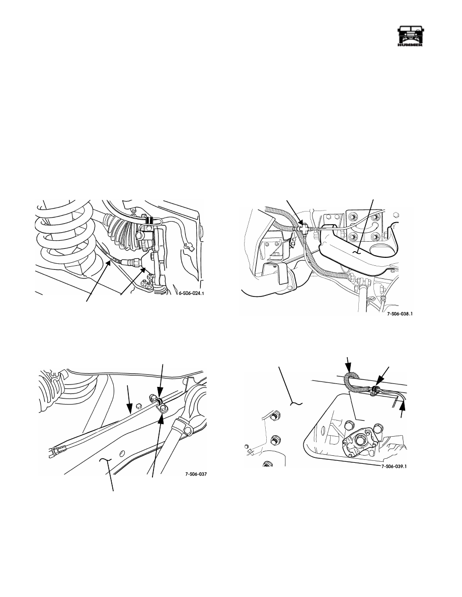
Figure 6-67: Front and Rear Supply Line
Connections
Figure 6-68: Supply Hose Connection
9-S06-013
REAR SUPPLY LINE
FRONT SUPPLY LINE
SUPPLY LINE
CROSSMEMBER
T-FITTING
6-50
Wheels and Tires/Central Tire Inflation System (CTIS)
_______________
®
FRONT CTI LINE REPLACEMENT
1.
Disconnect line at front hub (Figure 6-69).
2.
Loosen clamp on bracket attached to lower control arm,
then move air line out of bracket (Figure 6-70).
3.
Disconnect front air line at T-fitting secured to front
crossmember.
4.
Cut tie straps and remove front air line.
5.
Tape ends of new line to prevent dirt entry. Then route line
to front wheel and T-fittings.
6.
Secure hose to fittings and in clamp on lower control arm
bracket.
7.
Install tie straps as needed.
Figure 6-69: Line Connection to Hub
Figure 6-70: Line Bracket and
Clamp Location
REAR CTI LINE REPLACEMENT
1.
Disconnect line at rear wheel and at T-fitting (Figure 6-71).
2.
Remove line from clamp on lower control arm and from
rear hub.
3.
If working on right rear line, remove clamp over
crossmember to remove line (Figure 6-72).
4.
Tape ends of new line to prevent dirt entry.
5.
Connect line to T-fitting and rear hub.
6.
Secure line in control arm clamp.
7.
If working on right rear line, secure line to crossmember
with clamp (Figure 6-72).
Figure 6-71: T-Fitting Location
Figure 6-72: Right Rear Line Routing Over Rear
Crossmember
AIR LINE TO
FRONT WHEEL
HUB
AIR LINE
LOWER CONTROL ARM
BRACKET
CLAMP
T-FITTING
LEFT REAR
UPPER CONTROL ARM
AIR LINE TO
REAR
RIGHT REAR WHEEL
AIR LINE
TO TEE
CROSSMEMBER
CLAMP
Нет комментариевНе стесняйтесь поделиться с нами вашим ценным мнением.
Текст