Hummer H1 (2002+). Manual — part 109

______________
Wheels and Tires/Central Tire Inflation System (CTIS) 6-51
®
05745159
AIR INTAKE LINE REPLACEMENT
Removal
1.
Raise and secure hood.
2.
Loosen hose clamp and disconnect air intake hose from
connector (Figure 6-73).
Figure 6-73: Air Intake Hose
3.
Loosen clamp and disconnect air cleaner elbow from air
horn.
4.
Remove nut, washer, coupling, connector, and seal from
air horn.
5.
Loosen hose clamp securing air intake hose to compressor
fitting (Figure 6-74).
Figure 6-74: Air Intake Hose to Fitting
6.
Remove air intake hose.
Cleaning and Inspection
Clean and inspect air intake hose, elbow, coupling assembly
and seal. Check for leaks, cracks, and stripped threads.
CAUTION: Do not allow sealant into air system. Sealant will
damage CTIS components.
NOTE: Apply sealant to threads prior to installation.
Installation
1.
Connect air intake hose to compressor fitting and secure
with hose clamp (Figure 6-74).
2.
Install seal, coupling, washer, nut, and connector to air
horn (Figure 6-73).
3.
Connect air cleaner elbow to air horn and secure with
clamp.
4.
Connect air intake hose to air horn connector and secure
with hose clamp.
5.
Lower and secure hood.
TUBE SHIELD REPLACEMENT
1.
Remove bolts, washers and tube shield from wheel.
2.
Install new CTIS decal on tube shield, if necessary.
3.
Install tube shield tab into slot on bracket.
4.
Secure tube shield to spindle with bolts and washers.
Figure 6-75: Tube Shield Assembly
AIR
INTAKE
HOSE
AIR
HORN
SEAL
ELBOW
CLAMP
CONNECTOR
CLAMP
9-S06-012
CLAMP
FITTING
AIR INTAKE
HOSE
TAB
TUBE SHIELD
SPINDLE
BRACKET
6-52
Wheels and Tires/Central Tire Inflation System (CTIS)
_______________
®
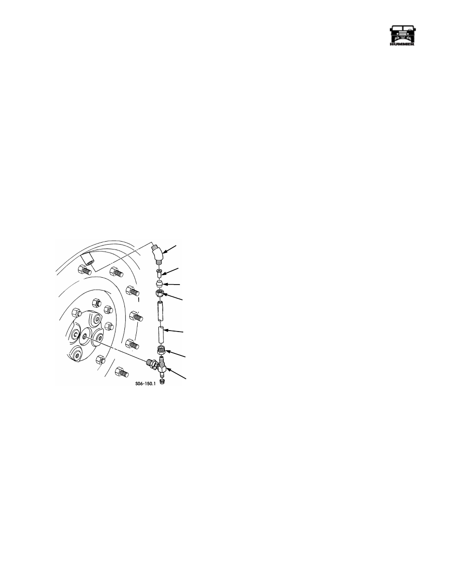
QUICK-DISCONNECT VALVE AND TUBE
REPLACEMENT
WARNING: CTIS components are subject to high air
pressure. Always relieve air pressure before loosening
or removing air system components by disconnecting
quick-disconnect valve assemblies. Failure to follow
this warning may result in serious injury.
NOTE: The replacement of all four quick-disconnect valves
and tube assemblies is identical.
Removal
1.
Raise and support vehicle.
2.
Remove tube shield.
3.
Remove tube and nut from quick-disconnect valve
(Figure 6-76).
Figure 6-76: Quick-Disconnect Valve Assembly
CAUTION: Do not force apart quick-disconnect valve. The
quick-disconnect valve is a one-piece component. Damage to
quick-disconnect valve will result if forced apart.
4.
Remove quick-disconnect valve from spindle.
5.
Disconnect tube from elbow, then remove nut and sleeve
assembly and insert from tube.
6.
Remove elbow.
Cleaning and Inspection
Clean and inspect tube and quick-disconnect valve. Check for
leaks, stripped threads, and cracks. Replace defective parts.
Installation
CAUTION: Do not allow sealant into air system. Sealant will
damage CTIS components.
NOTE: Apply sealant to threads prior to installation.
1.
Install quick-disconnect valve into spindle (Figure 6-76).
2.
Install elbow.
3.
Install nut on tube and connect tube to quick-disconnect
valve.
4.
Install nut and sleeve assembly and insert on tube and
connect tube to elbow.
5.
Install tube shield.
6.
Lower vehicle.
QUICK
DISCONNECT
VALVE
NUT
TUBE
INSERT
ELBOW
NUT
SLEEVE

______________
Wheels and Tires/Central Tire Inflation System (CTIS) 6-53
®
05745159
REAR TUBE CONNECTION SHIELD
REPLACEMENT
NOTE: The replacement of the left and right rear tube connec-
tion shields is basically the same. This procedure covers the
left rear tube connection shield.
Removal
Remove two bolts, washers, shield, and two washers from
steering arm cover (Figure 6-77).
Cleaning and Inspection
Clean and inspect shield and mounting hardware. Check for
cracks and stripped threads. Replace defective parts.
Figure 6-77: Rear Tube Connection Shield
Installation
Install shield on steering arm cover with two washers, bolts,
and two washers. Tighten bolt to 75 lb-ft (102 N•m)
(Figure 6-77).
GEARED HUB REPLACEMENT (CTIS)
WARNING: CTIS components are subject to high air
pressure. Always relieve air pressure before loosening
or removing air system components by disconnecting
quick-disconnect valve assemblies. Failure to follow
this warning may result in serious injury.
NOTE: The geared hub spindle has been bored to allow a di-
rect air passage through the spindle to the quick-disconnect
valve assembly. The front of the spindle is bored and tapped to
allow installation of a quick-disconnect coupling. The rear of
the spindle is bored for the insertion of a spindle extension,
which creates an air-tight passageway into the steering arm
cover. A bored hole in the steering arm cover allows the instal-
lation of a rotary seal and an air line, which routes compressed
air to the tires.
Removal
1.
Remove tube shield.
2.
Remove rear tube connection shield.
Figure 6-78: Line Connection at Steering
Arm Cover
3.
Remove line fitting from steering arm cover (Figure 6-78).
4.
Remove geared hub.
Installation
1.
Install geared hub.
2.
Apply sealant to line fitting and install in steering arm
cover (Figure 6-78).
3.
Install rear tube connection shield.
4.
Install tube shield.
STEERING
ARM COVER
SHIELD
STEERING
ARM COVER
LINE FITTING
AIR LINE
7-S06-036.2

6-54
Wheels and Tires/Central Tire Inflation System (CTIS)
_______________
®
SPINDLE EXTENSION AND SEAL
REPLACEMENT
Removal
1.
Remove rear tube connection shield.
2.
Remove four bolts, washers, and steering arm cover from
geared hub (Figure 6-79).
3.
Remove retaining ring and seal from steering arm cover.
4.
Remove spindle extension from spindle.
Figure 6-79: Spindle Extension and Seal
Cleaning and Inspection
Clean and inspect spindle extension and seal. Check for leaks
and cracks. Replace defective parts.
Installation
CAUTION: Do not allow sealant or adhesive into air system.
Sealant will damage CTIS components.
1.
Apply sealant to seal and install seal in steering arm cover
(Figure 6-79).
2.
Secure seal to steering arm cover with retaining ring.
3.
Apply a small amount of adhesive to end of spindle
extension and install into spindle.
4.
Install steering arm cover on geared hub with four washers
and bolts. Tighten bolts to 75 lb-ft (102 N•m).
5.
Install rear tube connection shield.
AUXILIARY AIR HOSE REPLACEMENT
Removal
1.
Raise and secure hood.
WARNING: The CTIS air system contains air under
high pressure. Always relieve air pressure before loos-
ening or removing air system component(s) by discon-
necting quick-disconnect valves. Failure to follow this
warning may result in personal injury.
2.
Isolate tire by depressing metal tab on quick-disconnect
valve body. The valve body will pop out approximately
1/4 in. (6 mm) from shuttle. Perform this procedure on
remaining three wheels (Figure 6-81).
Figure 6-80: CTIS Quick-Disconnect Valve
3.
Remove auxiliary air valve from tee (Figure 6-81).
STEERING
ARM COVER
SEAL
RETAINING
RING
EXTENSION
GEARED
HUB
DISCONNECTED
CONNECTED
VALVE
BODY
TAB
SHUTTLE
Нет комментариевНе стесняйтесь поделиться с нами вашим ценным мнением.
Текст