Hummer H1 (2002+). Manual — part 206
______________________________________________________
Electrical System 12-51
®
05745159
IGNITION SWITCH REPLACEMENT
Removal
1.
Remove steering column covers.
2.
Remove multi switch.
3.
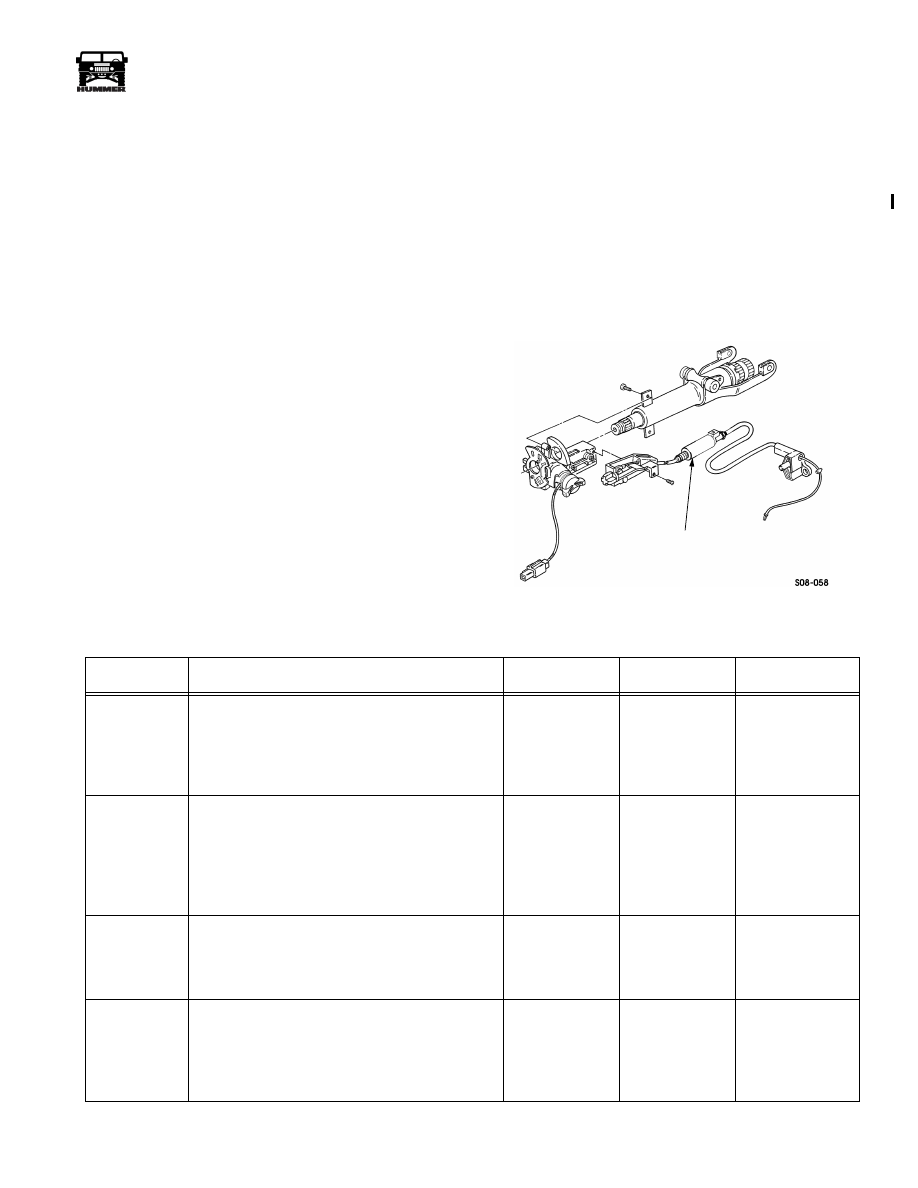
Remove screw and interlock cable from ignition switch
(Figure 2-76).
4.
Remove two capscrews and ignition switch from steering
column.
Installation
1.
Apply thread-locking compound to capscrew threads and
install ignition switch on steering column with two cap-
screws.
2.
Install interlock cable on ignition switch with screw.
3.
Install multi switch.
4.
Install steering column covers.
5.
Ensure ignition switch operates properly.
Brake Shift Interlock Cable System Descrip-
tion (Figure 2-76)
The purpose of the brake shift interlock cable is to prevent a
driver from engaging a transmission gear before the brakes are
applied. When the brake pedal is depressed, voltage from the
brake switch de-energizes the interlock solenoid and the cable
relaxes. The transmission shift lever can then be pulled out of
the park position. If electrical power is lost due to a dead bat-
tery or system failure, the solenoid defaults to the open posi-
tion. With the brake/shift interlock solenoid in the open
position the shifter may be moved to any position.
Figure 2-76: Brake Shift Interlock Cable
SOLENOID
Brake Shift Interlock Cable Inoperative
STEP
ACTION
VALUES
YES
NO
1
Gain access to the brake/shift interlock solenoid.
Using a DVOM check for ground on the black
wire (CKT 59). Does the resistance meet the
specifications?
<.2
Ω
Go to step 2.
Repair the open or
bad connection in
CKT 59 between
the interlock sole-
noid and G4.
2
With the ignition switch in the “run” position
check the voltage at the tan wire (CKT 83). Is the
specified voltage present?
12v
Go to step 3.
Repair the open or
bad connection in
CKT 83 between
the interlock cable
and fuse 1C in the
interior fuse box.
3
With the ignition switch in the “run” position and
the brake switch applied check the voltage at the
red wire (CKT 22) on the brake shift interlock
solenoid. Is the specified voltage present?
12v
Replace the
brake shift inter-
lock cable.
Go to step 4.
4
Gain access to the brake switch. With a DVOM
check the voltage at the orange wire (CKT 10). Is
the specified voltage present?
12v
Replace the
brake switch.
Repair the open or
bad connection on
CKT 10 between
the brake switch
and fuse 4D.
3-1-01
12-52
Electrical System
_______________________________________________________
®
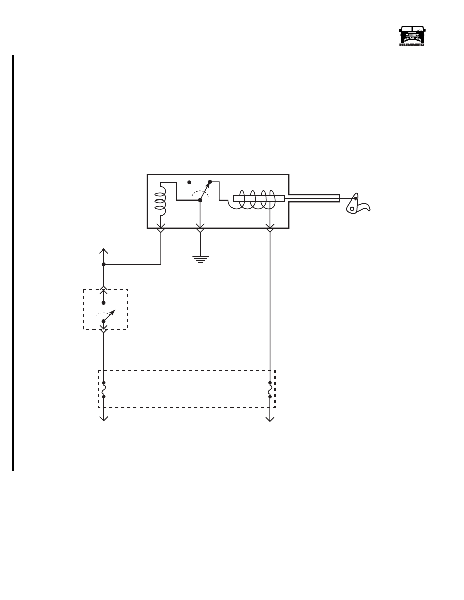
Figure 2-77: Shift Interlock Cable Schematic
59 BK
FUSE
4D
15 AMP
INTERIOR
FUSE
BOX
INTERLOCK CABLE SOLENOID
83 TN
G4
TO
TURN SIGNAL
SWITCH
BRAKE
SWITCH
TO
BATTERY
22 RD
FUSE
1C
5 AMP
INTERIOR
FUSE
BOX
TO
IGNITION
9-S12-001
INTERIOR FUSE BOX
10 OR
4-1-00

______________________________________________________
Electrical System 12-53
®
05745159
CTIS Compressor Inoperative
Step
Action
Value(s)
Yes
No
1
Using a DVOM set to measure voltage, probe the
terminals on the CTIS compressor. With the CTIS
compressor switch set to inflate, and the ignition
on, is voltage present?
12v
Replace the
compressor
Go to step 2.
2
Move the ground lead to a known good ground
and the positive lead still on the compressor, igni-
tion on, compressor switch on inflate. Is voltage
present?
12v
Repair open or
bad connection
in CKT57
between com-
pressor and G2.
Go to step 3.
3
Remove compressor relay from the exterior fuse
box. Using a DVOM set to measure voltage,
Probe cavity 1(CKT46) of the CTIS compressor
relay socket with the positive lead, and cavity
2(CKT59) with the negative lead. Ignition on,
CTIS compressor switch to on, is voltage present?
12v
Go to step 7.
Go to step 4.
4
Using a DVOM set to measure voltage, check
continuity to ground at cavity 2 of the compressor
relay socket. Is resistance below specification?
<.2
Ω
Go to step 5.
Repair open or
bad connection
in CKT59
between com-
pressor relay
and G2.
5
Remove compressor switch from the dash. Using
a DVOM set to measure voltage. Ignition on,
compressor switch set to inflate. Check for volt-
age on white wire(CKT46). Is voltage present?
12v
Repair open or
bad connection
in CKT46
between com-
pressor switch
and relay.
Go to step 6.
6
Using a DVOM set to measure voltage, turn the
ignition on. Check for voltage at both orange
wires(CKT640) at the rear of the compressor
switch. Is voltage present?
12v
Replace the
compressor
switch.
Repair open,
bad connection
or short in
CKT640
between com-
pressor switch
and fuse 1G.
7
Using a DVOM set to measure continuity mea-
sure continuity between cavity 5(CKT437) of the
compressor relay socket and the green
wire(CKT437) at the compressor. Is resistance
below specifications?
<.2
Ω
Go to step 8.
Repair open,
bad connection,
or short in
CKT437
between relay
and compressor.
8
Using a DVOM set to measure voltage, place the
positive lead in cavity 3 (CKT436) of the com-
pressor relay. Place the ground lead in cavity
86(CKT59). Is voltage present?
<.2
Ω
Replace the
compressor
relay.
Repair open,
bad connection
or short in
CKT436
between com-
pressor relay
and Maxi
fuse#6.
4-1-00

12-54
Electrical System
_______________________________________________________
®
CTIS Exhaust Valve Inoperative
Step
Action
Value(s)
Yes
No
1
Disconnect exhaust solenoid. Using a DVOM set
to measure voltage, probe the light green
wire(CKT47) with the positive lead, and the black
wire(CKT57) with the negative lead. Ignition on,
move the compressor switch to deflate. Is voltage
present?
12v
Replace exhaust
solenoid.
Go to step 2.
2
Check continuity to ground on the black
wire(CKT57) at the exhaust solenoid. Is resis-
tance below specification?
<.2
Ω
Go to step 3.
Repair open or
bad connection
in CKT57
between exhaust
solenoid and
G2.
3
Remove compressor switch. Using a DVOM set
to measure voltage, check for voltage at both
orange wires (CKT640). With ignition on is volt-
age present?
12v
Go to step 4.
Repair open,
bad connection
or short in
CKT640
between com-
pressor switch
and fuse 1G.
4
Using a DVOM set to measure voltage, check for
voltage at the light green wire(CKT47) with the
ignition on and compressor switch to deflate. Is
voltage present?
12v
Repair open bad
connection or
short in CKT 47
between com-
pressor switch
and exhaust
solenoid.
Replace com-
pressor switch.
4-1-00
Нет комментариевНе стесняйтесь поделиться с нами вашим ценным мнением.
Текст