Hummer H1 (2002+). Manual — part 205
______________________________________________________
Electrical System 12-47
®
05745159
Fuel Tank Selector System Inoperative (No Tank Switch)
Step
Action
Value(s)
Yes
No
1
Important: Before clearing the DTC’s use the
scan tool Capture Info in order to record the
Freeze Frame and the failure records for refer-
ence, as the data will be lost when the clear func-
tion is used.
Was the On-Board Diagnostic (OBD) System
Check performed?
Go to step 2.
Go to Power-
train OBD sys-
tem check.
2
Turn the ignition OFF for 10 seconds. Turn the
ignition ON. Does the fuel pump operate during
the glow plug cycle?
Go to step 3.
Diagnose Fuel
lift pump first.
3
Remove fuel tank selector switch from dash, and
disconnect switch from harness. Using a DVOM
set to measure resistance, probe the black wire of
the fuel selector switch connector (CKT 59) with
the black lead, and the positive lead on the ground
studs at left of dash.Is resistance below specifica-
tion?
<.2
Ω
Go to step 4
Repair open or
bad connection
in CKT 59
between fuel
selector switch
and IP ground
studs.
4
Using a DVOM set to measure voltage, place the
ground lead on the negative studs to right of the
IP panel. Place the positive lead on the grey wire
(CKT 787) at the fuel tank selector switch. Turn
the ignition OFF for 10 seconds. Turn the ignition
ON. Does the meter read voltage?
12 v
Go to step 5
Repair open or
short to ground
in CKT 787 fuel
pump relay and
fuel selector
switch
5
Re-connect fuel tank selector switch. Using a
DVOM set to measure voltage, backprobe the red
wire (CKT 786) with the negative lead and brown
wire (CKT 789) with the positive lead.Turn the
ignition OFF for 10 seconds. Turn the ignition
ON. With the switch in the AUX position voltage
should be present, when the switch is moved to
the MAIN position, reverse polarity voltage
should be present. If fuel pump shuts off during
test, repeat cycle of key. Does meter show oppo-
site voltages when moved between AUX and
MAIN
12 v+=AUX
12 v-=MAIN
Go to step 5.
Replace fuel
tank selector
switch and
recheck system.
6
Disconnect fuel selector valve electrical connec-
tion. Using a DVOM set to measure voltage,
probe the brown wire with the positive lead, and
the red lead with the negative lead. Turn the igni-
tion OFF for 10 seconds. Turn the ignition ON.
With the switch in the AUX position voltage
should be present, when the switch is moved to
the MAIN position, reverse polarity voltage
should be present. Does meter show opposite
voltages when moved between AUX and MAIN
12 v+=AUX
12 v-=MAIN
Replace fuel
selector valve
Go to step 7.
4-1-00
12-48
Electrical System
_______________________________________________________
®
7
Relocate the ground lead of the DVOM set to
measure voltage to a known good ground. Turn
the ignition OFF for 10 seconds. Turn the ignition
ON, and the tank selector switch in the AUX posi-
tion, probe the brown wire (CKT 789) with the
positive meter lead. Is voltage present?
12 v
Go to step 8.
Repair open,
bad connection
or short to
ground in CKT
789 between the
fuel selector
switch and
valve.
8
Turn the ignition OFF for 10 seconds. Turn the
ignition ON, and the tank selector switch in the
MAIN position, probe the red wire (CKT 786)
with the positive meter lead, the ground lead
should be on a know good ground. Is voltage
present?
12 v
No electrical
problems found,
problem may be
intermittent or
mechanical.
Repair open,
bad connection
or short to
ground in CKT
786.
Fuel Tank Selector System Inoperative (No Tank Switch)
Step
Action
Value(s)
Yes
No
4-1-00
______________________________________________________
Electrical System 12-49
®
05745159
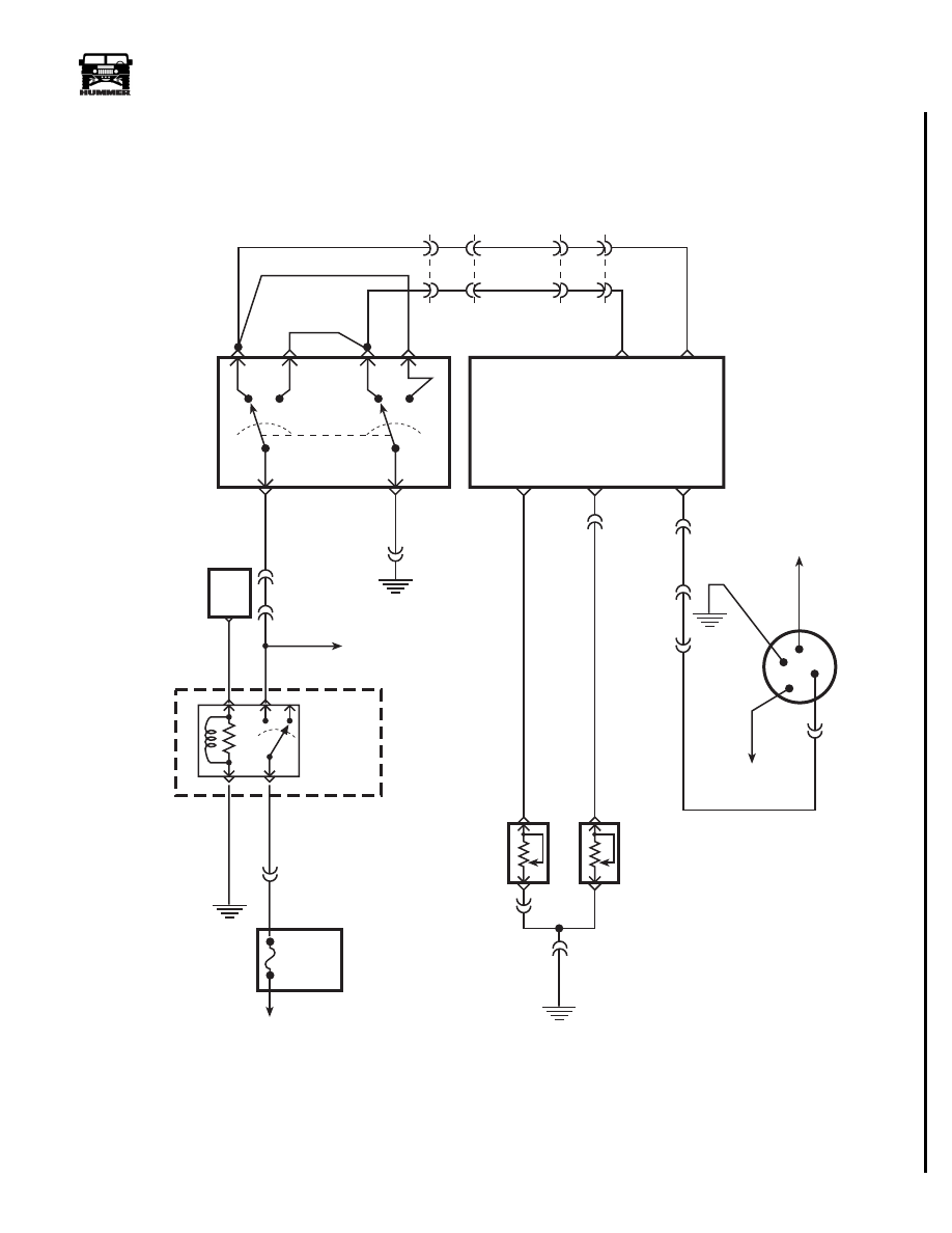
Figure 2-74: Fuel Selector Valve Schematic
EXTERIOR
FUSE BOX
G2
G4
FUSE 2D
20A
INTERIOR
FUSE BOX
HOT AT
ALL TIMES
FUEL
SELECTOR
SWITCH
G4
TO DIMMER
MODULE
FUEL
GAUGE
TO
GAUGE
FUSE
I
G
L
S
FUEL
SELECTOR
VALVE
FUEL LEVEL
SIGNAL OUT
17 PP
30 GY
29 PK
C26-B
C2-35
C1-35
AUX TANK
FUEL LEVEL
SIGNAL
MAIN TANK
FUEL LEVEL
SIGNAL
TANK
CHANGE
CONTROL
TANK
CHANGE
CONTROL
C26-C
675 YL
673 DB
C1
C3
C2
C26
75
M6
37
E
9
M7
36
D
786 RD
3
789 BR
1
6
4
2B
5B
C3-N6
59 BK
787 GY
C3-M8
C1-11
TO FUEL
LIFT
PUMP
C27-D8
85
87 87A
86
30
PCM
C1-10
537 OR
9-S12-057
59 BK
FUEL
LIFT PUMP
RELAY
238 DG
G2
A
AUX TANK
FUEL LEVEL
SENDING UNIT
MAIN TANK
FUEL LEVEL
SENDING UNIT
59 BK
C26-A
B
C38-C
C3-P7
Training 8F
4-1-00
12-50
Electrical System
_______________________________________________________
®
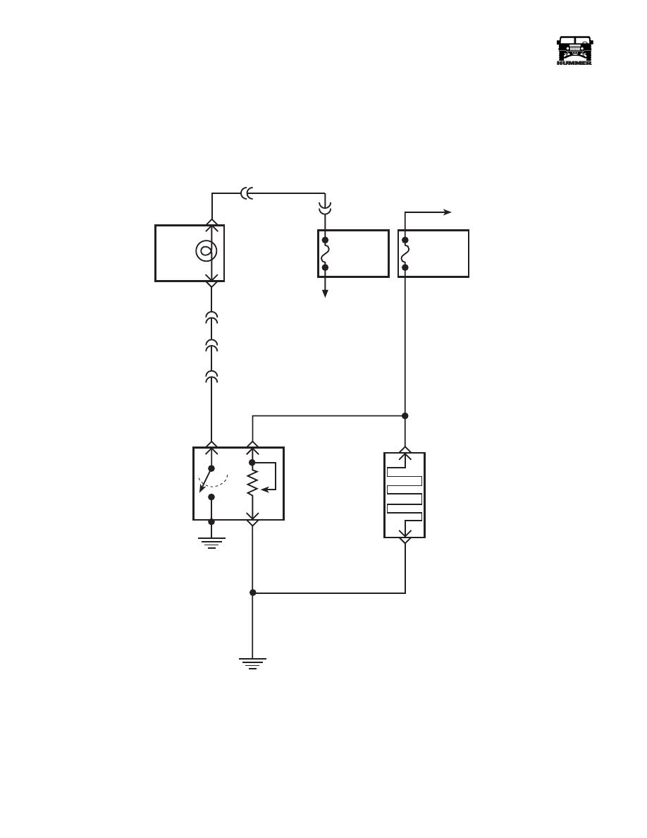
Figure 2-75: Fuel Manager Schematic
FUSE 3B
20AMP
EXTERIOR
FUSE BOX
DRAIN
FILTER
HOT IN RUN
AND START
WATER IN
FUEL LIGHT
LEFT HAND
STATUS CENTER
C9-D
C3-F4
C1-45
B
A
327 YL
C
C9-J
WATER IN
FUEL
SENSOR
FUEL
HEATER
291 PK
57 BK
G2
57 BK
C
A
9-S12-154
FUSE 4B
5AMP
INTERIOR
FUSE BOX
TO
IGNITION
SWITCH
C3-N7
30 GY
4-1-00
Нет комментариевНе стесняйтесь поделиться с нами вашим ценным мнением.
Текст