Hummer H1 (2002+). Manual — part 207

______________________________________________________
Electrical System 12-55
®
05745159
CTIS Front Inflate Valve Inoperative
Step
Action
Value(s)
Yes
No
1
Disconnect front inflate solenoid. Using a DVOM
set to measure voltage connect the positive lead to
the tan wire(CKT91), and the negative lead to the
black wire(CKT57). With the ignition on, selector
switch set to both, and the compressor switch to
inflate, is voltage present?
12v
Replace front
inflate solenoid.
Go to step 2.
2
Check continuity to ground on the black
wire(CKT57) at the front inflate solenoid. Is resis-
tance below specification?
<.2
Ω
Go to step 3.
Repair open or
bad connection
in CKT57
between front
inflate valve
and G2.
3
Remove selector switch and compressor switch
from the I/P. Using a DVOM set to measure volt-
age, ignition on, and compressor switch set to
inflate. Check for voltage on both yellow
wires(CKT144) at rear of selector switch. Is volt-
age present.
12v
Go to step 6.
Go to step 4.
4
Ignition on, compressor switch on inflate, check
for voltage on yellow wires(CKT144)at rear of
compressor switch. Is voltage present?
12v
Repair open,
bad connection
or short in
CKT144
between com-
pressor switch
and selector
switch.
Go to step 5.
5
Ignition on, check for voltage at both orange
wires(CKT640) at back of compressor switch. Is
voltage present?
12v
Replace com-
pressor switch.
Repair open,
bad connection
or short in
CKT640
between com-
pressor switch
and fuse 1G.
6
Ignition on, compressor switch set to inflate,
selector switch set to both. Check for voltage at
the tan wire(CKT91) at the back of the selector
switch. Is voltage present?
12v
Repair open,
bad connection,
or short in
CKT91 between
selector switch
and front inflate
valve.
Replace the
selector switch.
4-1-00

12-56
Electrical System
_______________________________________________________
®
CTIS Rear Inflate Valve Inoperative
Step
Action
Value(s)
Yes
No
1
Disconnect front inflate solenoid. Using a DVOM
set to measure voltage connect the positive lead to
the grey wire(CKT92), and the negative lead to
the black wire(CKT57). With the ignition on,
selector switch set to both, and the compressor
switch to inflate, is voltage present?
12v
Replace rear
inflate solenoid.
Go to step 2.
2
Check continuity to ground on the black
wire(CKT57) at the rear inflate solenoid. Is resis-
tance below specification?
<.2
Ω
Go to step 3.
Repair open or
bad connection
in CKT57
between rear
inflate solenoid
and G2.
3
Remove selector switch and compressor switch
from the I/P. Using a DVOM set to measure volt-
age, ignition on, and compressor switch set to
inflate. Check for voltage on both yellow
wires(CKT144) at rear of selector switch. Is volt-
age present.
12v
Go to step 6.
Go to step 4.
4
Ignition on, compressor switch on inflate, check
for voltage on yellow wires(CKT144)at rear of
compressor switch. Is voltage present?
12v
Repair open,
bad connection
or short in
CKT144
between com-
pressor switch
and selector
switch.
Go to step 5.
5
Ignition on, check for voltage at both orange
wires(CKT640) at back of compressor switch. Is
voltage present?
12v
Replace com-
pressor switch.
Repair open,
bad connection
or short in
CKT640
between com-
pressor switch
and fuse 1G.
6
Ignition on, compressor switch set to inflate,
selector switch set to both. Check for voltage at
the grey wire(CKT92) at the back of the selector
switch. Is voltage present?
12v
Repair open,
bad connection,
or short in
CKT92 between
selector switch
and front inflate
valve.
Replace the
selector switch.
4-1-00
______________________________________________________
Electrical System 12-57
®
05745159
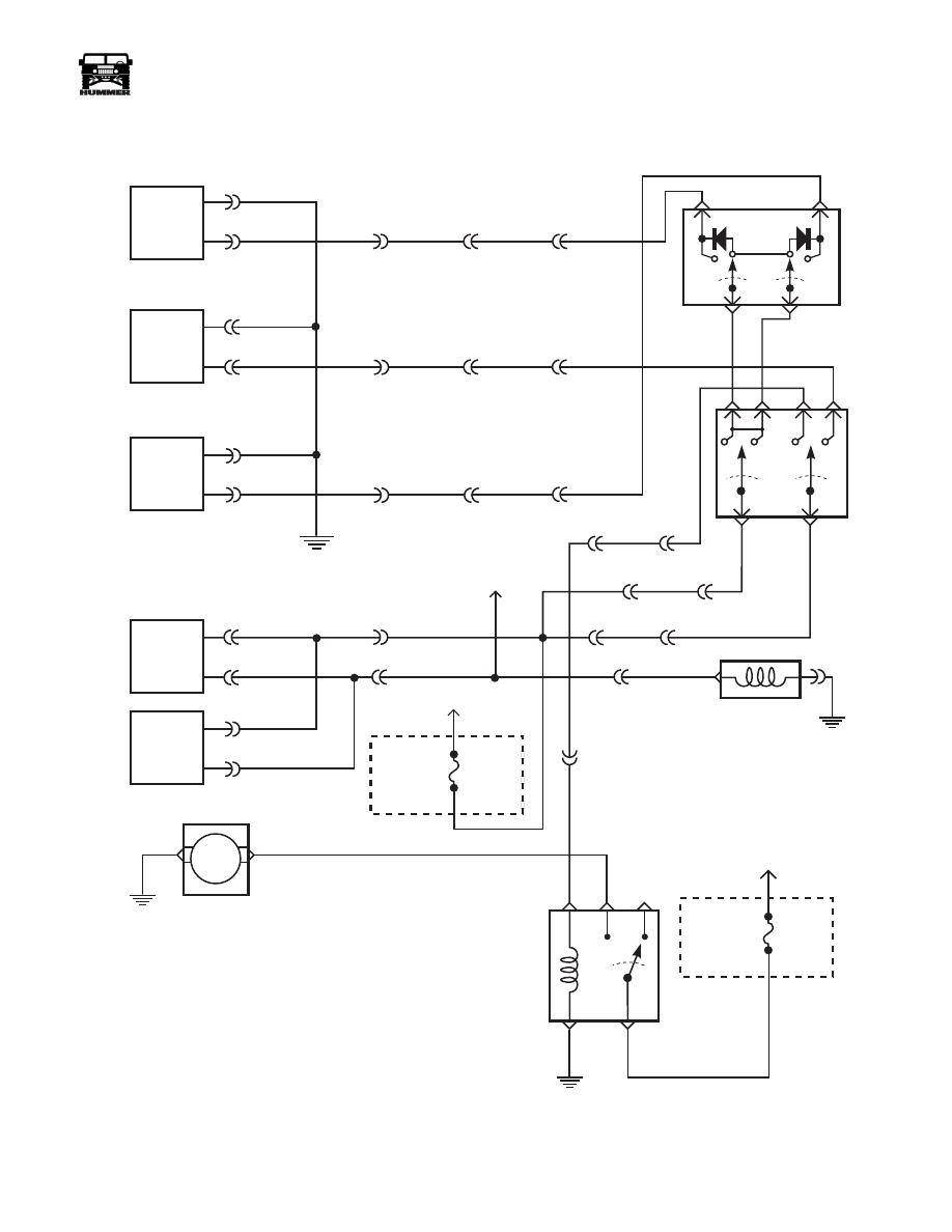
Figure 2-78: CTIS Schematic
REAR
SOL
DEFLATE
SOL
FRONT
SOL
FRONT
LOW
PRESSURE
REAR
LOW
PRESSURE
57 BK
92 GY
57 BK
47 LG
57 BK
91 TN
A
B
A
B
A
B
G2
640 OR
428 PK
640 OR
428 PK
C1-24
C1-58
C1-63
C1-23
C1-57
C3-C4
C3-C2
C3-C3
R
F
C12-F
C12-D
C12-E
WARNING LAMP
MINI
FUSE
1G
5 AMP
INTERIOR
FUSE
BOX
CTIS
WARNING
M
MAXI
FUSE
6
30 AMP
ENGINE
FUSE
BOX
CTIS
COMPRESSOR
CTIS
COMPRESSOR
TIRE
SELECTOR
144 YL
144 YL
INFLATE/
DEFLATE
STATUS
CENTER
IP
TO BUZZER
(fuse box)
COMPRESSOR
RELAY
57 BK
G2
437 DG
G3
59 BK
436 YL
46 WH
C1-59
C3-G4
G4
59 BK
C12-K
C3-B4
C12-G
C3-B3
C12-H
C3-B4
C12-J
TO
BATTERY
9-S12-002
4-1-00

12-58
Electrical System
_______________________________________________________
®
Figure 2-79: Lights Schematic (Sheet 1 of 2)
9-S12-006.1
SIDE MARKER
CLEARANCE PARK/TURN
HEAD
LIGHTS
13TN
3 LB
12 DR
58 BK
20 RD
2 LG
CLEARANCE
PARK/TURN
SIDE MARKER
3 LB
2 LG
80 WH
80 WH
58 BK
12 DR
13TN
58 BK
20 RD
UNDER
HOOD
LAMP
HOOD
HARNESS
A B
C
A
B
C
D
G4
C2-2
C1-73
C2-3
C1-65
C2-4
C1-66
C2-5
C1-47
C2-6
46
C2-7
C1-41
IDENTIFICATION
SIDE MARKER
ID
STOP/
TAIL/ TURN
BACKUP
G1
ID
59 BK
5 DG
21 GY
59 BK
21 GY
9 YL
140 OR
29
C2-30
C2-25
C1-74
C1-72
5 DG
21 GY
C1-71
TO IP
INDICATOR
LAMPS
G3
BACKUP
STOP/
TAIL/ TURN
SIDE MARKER
IDENTIFICATION
4-1-00
Нет комментариевНе стесняйтесь поделиться с нами вашим ценным мнением.
Текст