Hummer H1 (2002+). Manual — part 130
_________________________________________________________
Steering System 8-27
®
05745159
Valve Body-Stub Shaft-Wormshaft Removal
and Disassembly
1.
Grasp splined end of stub shaft and carefully rotate valve
body/stub shaft assembly out of gear housing.
2.
If wormshaft remained engaged in stub shaft cap,
disengage and remove wormshaft at this time.
3.
Remove O-ring from cap end of stub shaft.
4.
Lightly tap splined end of stub shaft on wood block to
disengage cap from valve body.
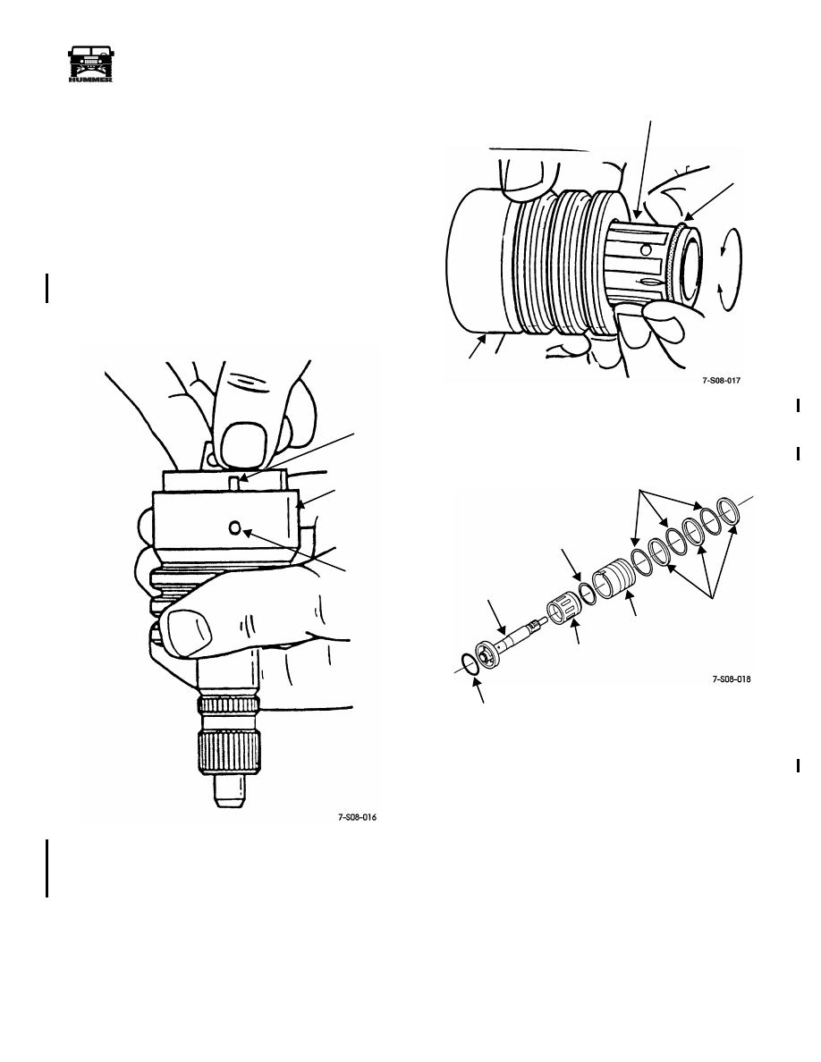
5.
Grasp stub shaft cap and pull it upward to expose shaft pin
(Figure 8-43). Then disengage shaft pin from valve body
and separate two components.
Figure 8-43: Stub Shaft Remova
l
6.
Remove spool from valve body with a rotating motion
(Figure 8-44).
Figure 8-44: Valve Spool Removal
7.
Remove O-ring from valve spool.
8.
Remove seals and O-rings from valve body (Figure 8-45).
Figure 8-45: Stub Shaft/Valve Body Components
NOTCH IN
VALVE
SHAFT
STUB SHAFT
CAP
BODY
PIN
VALVE SPOOL
O-RING
ROTATE
VALVE
SPOOL
TO REMOVE
BODY
STUB
STUB
VALVE
SPOOL
VALVE
SEAL RINGS
O-RINGS
O-RING
SHAFT
SPOOL
BODY
SHAFT
O-RING
4-1-00
8-28
Steering System
__________________________________________________________
®
Pitman Shaft Bearing and Seal Removal
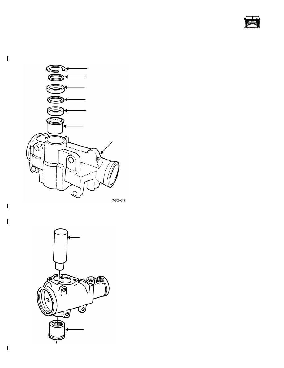
1.
Remove seal retaining ring with internal-type snap ring
pliers.
2.
Remove first backup washer (Figure 8-46).
Figure 8-46: Pitman Shaft Bearing and Seal Position
3.
Remove seals, second backup washer, and bearing with
tool J–6278 (Figure 8-47).
Figure 8-47: Pitman Shaft Bearing Removal
POWER STEERING GEAR CLEANING AND
INSPECTION
Discard all the old O-rings, seals, and seal rings. Do not reuse
these parts.
Clean the gear housing and components in a standard parts
cleaning solution and either wipe them dry with lint-free shop
towels or use low pressure compressed air.
Examine the wormshaft, pitman shaft, and stub shaft bearings
for wear, galling, flat spots, or loss of bearing material (flak-
ing). Also examine the wormshaft and stub shaft thrust bear-
ing races for wear, grooving, discoloration, scoring, or
spalling. Replace bearings and races as necessary. Do not re-
use parts in marginal condition.
Check the gear housing for cracks, damaged threads, scored-
worn valve bores, and damaged pressure hose seats. Replace
the housing if necessary. The hose seats can be replaced if
scored, distorted, or loose. Refer to the procedure in the assem-
bly and adjustment section.
Inspect condition of the rack piston, wormshaft, and recirculat-
ing bearing balls (Figure 8-48). Replace the bearing balls as a
set if any are scored, worn, distorted, have flat spots, or the
coating is flaking off. The rack piston should be free from
wear and scoring. Also be sure the seal ring groove is in good
condition and the edges are not chipped cracked, or peened
over. The wormshaft must be smooth and free of scoring or
wear to operate properly. Check the ball guide clamp threads in
the rack piston. Rough threads can be cleaned up with a tap but
damaged threads mean the rack piston will have to be replaced.
Check fit of the spool in the valve body. The spool should
move freely with a light coating of power steering fluid on it.
Replace the valve body and spool as an assembly if either part
is worn, scored, or damaged in any fashion.
Inspect the stub shaft for wear and damage. Minor nicks and
scratches on the shaft surface can be dressed off with crocus
cloth or 600 grit emery cloth wetted with oil. However, replace
the shaft if scored, or distorted.
The adjuster plug threads and bearing bore should be in good
condition especially the threads. Replace the plug if the threads
are rough, deformed, or chipped. Rough threads will prevent
proper preload on the wormshaft thrust bearing.
Examine the pitman shaft, side cover, and gasket. Replace the
shaft if the sector teeth are damaged, or the bearing and seal
contact surfaces are worn, scored, or damaged in any way.
Check condition of the side cover bushing. Replace the cover if
the bushing is worn as the bushing is not serviceable. Inspect
condition of the lash adjuster screw in the pitman shaft. Re-
place the shaft if the screw is damaged as the screw is not ser-
viced separately.
RETAINING RING
BACKUP WASHER
DOUBLE-LIP SEAL
BACKUP WASHER
SINGLE-LIP SEAL
PITMAN SHAFT BEARING
GEAR HOUSING
TOOL J–6278 OR J–21551
PITMAN SHAFT
BEARING
7-S08-020
4-1-00

_________________________________________________________
Steering System 8-29
®
05745159
Figure 8-48: Power Steering Gear Components
END PLUG
END PLUG
RACK PISTON
RACK PISTON
ADJUSTER
SIDE COVER
GASKET
ADJUSTER SCREW
PITMAN
HOSE
WORMSHAFT
WORMSHAFT
RACES
PITMAN SHAFT
SINGLE-LIP
DOUBLE-LIP
SNAP
SEAL RINGS
O-RINGS
VALVE
SPOOL
VALVE
STUB
STUB SHAFT
LOCKNUT
SNAP RING
DUST
OIL SEAL
STUB SHAFT
ADJUSTER
O-RING
INNER
THRUST
OUTER
SPACER
RETAINER
NUT AND
BACKUP
RACK PISTON
PISTON PLUG
BEARING
BALL
GUIDE
END PLUG
RACE
PLUG
BEARING
BEARING
SEAL
RACE
O-RING
BODY
SPOOL
SHAFT
O-RING
LOCKWASHER
WASHERS
SEAL
SEAL
BEARING
RING
CLAMP
GUIDES
BALLS (24)
RETAINING
RING
THRUST
BEARING
SEATS
SHAFT
BACKUP O-RING
NUT
O-RING
SEAL RING
4-1-00
8-30
Steering System
__________________________________________________________
®
POWER STEERING GEAR ASSEMBLY AND
ADJUSTMENT
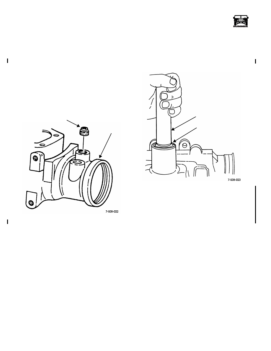
Gear Housing Hose Seat Replacement
The hose seats in the gear housing (Figure 8-49), can be re-
placed when necessary. Procedure is as follows:
1.
Thread appropriate size pan head, hardened sheet metal
screw into seat.
2.
Pry old seat out of housing using pry tools positioned
under screw head.
3.
Clean gear housing afterward to remove any chips.
4.
Install new seat using spare hose fitting and brass punch.
Figure 8-49: Pressure Hose Seat
Pitman Shaft Bearing and Seal Installation
1.
Lubricate bearing and seals with power steering fluid, or
petroleum jelly.
2.
Install bearing in gear housing with handle J–8092 and
installer J–6278 or J–21551 (Figure 8-50).
Figure 8-50: Pitman Shaft Bearing Installation
3.
Install single lip seal in housing with tool J–6219
(Figure 8-51). Be sure seal lip is toward gear housing.
4.
Install backup washer on single lip seal (Figure 8-51).
5.
Install double lip seal in housing with tool J–6219
(Figure 8-51). Be sure seal lip is toward gear housing.
6.
Install backup washer on double lip seal.
7.
Install seal retaining snap ring.
PRESSURE
HOUSING
HOSE
SEAT
TOOL HANDLE J–8092
INSTALLER TOOL
J–6278 OR J–21551
4-1-00
Нет комментариевНе стесняйтесь поделиться с нами вашим ценным мнением.
Текст