Hummer H1 (2002+). Manual — part 129

_________________________________________________________
Steering System 8-23
®
05745159
13. Turn steering wheel lightly against each stop and record
maximum pressure.
a.
If pressure at each stop is about the same as recorded
in step 10, and flow drops to 0.5 gpm (1.85 L/min.),
continue with test.
b.
If pressures does not reach maximum recorded in step
10, and flow rate does not fall off, overhaul steering
gear to correct internal leakage in valve, or past seal
rings.
14. Turn steering wheel to the right, release it., and observe
the analyzer gauge. Then turn the wheel to the left, release
it, and observe the gauge again.
a.
If the gauge needle indicates normal pressure then
snaps back as the wheel is released. Continue the test.
b.
If the gauge indicates normal pressure but the needle
is slow to return when the wheel is released, the steer-
ing gear valve body or spool is sticking. Overhaul will
be required to correct the problem.
15. If gear and pump test OK but a problem still exists, check
for fluid contamination. Draw off sample with suction gun
and empty sample in glass container. Look for burned
fluid, foreign material, fluid layering (fluid separates into
two layers), foreign material/metal particles in the fluid.
Any of these conditions will cause gear and pump
problems. Flushing the system with new fluid may correct
the problem.
16. If fluid condition is OK but a problem still exists, a
problem may exist in the steering linkage, tires/wheels, or
suspension part. Further diagnosis will be required.
Figure 8-30: Analyzer Pressure Test Connections
POWER STEERING GEAR DISASSEMBLY AND
OVERHAUL
Cleanliness is extremely important to a successful gear over-
haul. Clean the gear exterior before disassembly and make sure
the workbench area is clean and dry. Drain as much of the old
fluid from the gear as possible beforehand. Dirt and foreign
material must not be allowed to enter the gear internal compo-
nents. Use lint free shop towels for wiping parts and hands
clean. Lint from cotton towels will flow through the system
and eventually cause the valve body spool, or pump control
valve to stick and bind.
Side Cover and Pitman Shaft Removal
1.
Remove side cover attaching bolts.
2.
Hold adjuster screw with hex wrench and remove adjuster
screw nut.
3.
Rotate stub shaft as necessary to center pitman shaft teeth
in rack piston. Use 12 point socket and ratchet to turn stub
shaft.
4.
Remove pitman shaft, side cover, and gasket (Figure 8-31).
Figure 8-31: Side Cover and Sector Shaft
FITTING
ANALYZER
ADAPTERS
J-25323
ADJUSTER
SIDE
GASKET
PITMAN
ADJUSTER
LOCKNUT
SHAFT
COVER
SCREW
4-1-00
8-24
Steering System
__________________________________________________________
®
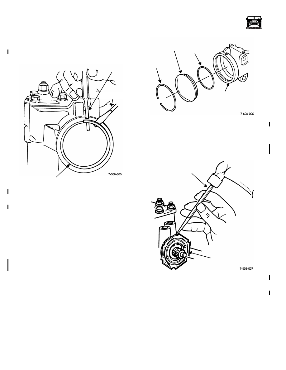
Gear Housing End Plug Removal
1.
Rotate end plug retaining ring until one end is under small
access hole in housing (Figure 8-32).
Figure 8-32: End Plug Retaining Ring Removal
2.
Unseat end plug retaining ring with small pin punch and
screwdriver (Figure 8-32). Insert punch through access
hole in housing as shown.
3.
Slowly rotate stub shaft counterclockwise to ease end
plug out of housing.
CAUTION:
Do not rotate the stub shaft any farther than nec-
essary. The recirculating balls can drop out of the rack piston
and fall inside the piston chamber making further disassembly
extremely difficult.
4.
Remove end plug (Figure 8-33).
5.
Remove O-ring seal from housing (Figure 8-33).
Figure 8-33: End Plug and Seal Removal
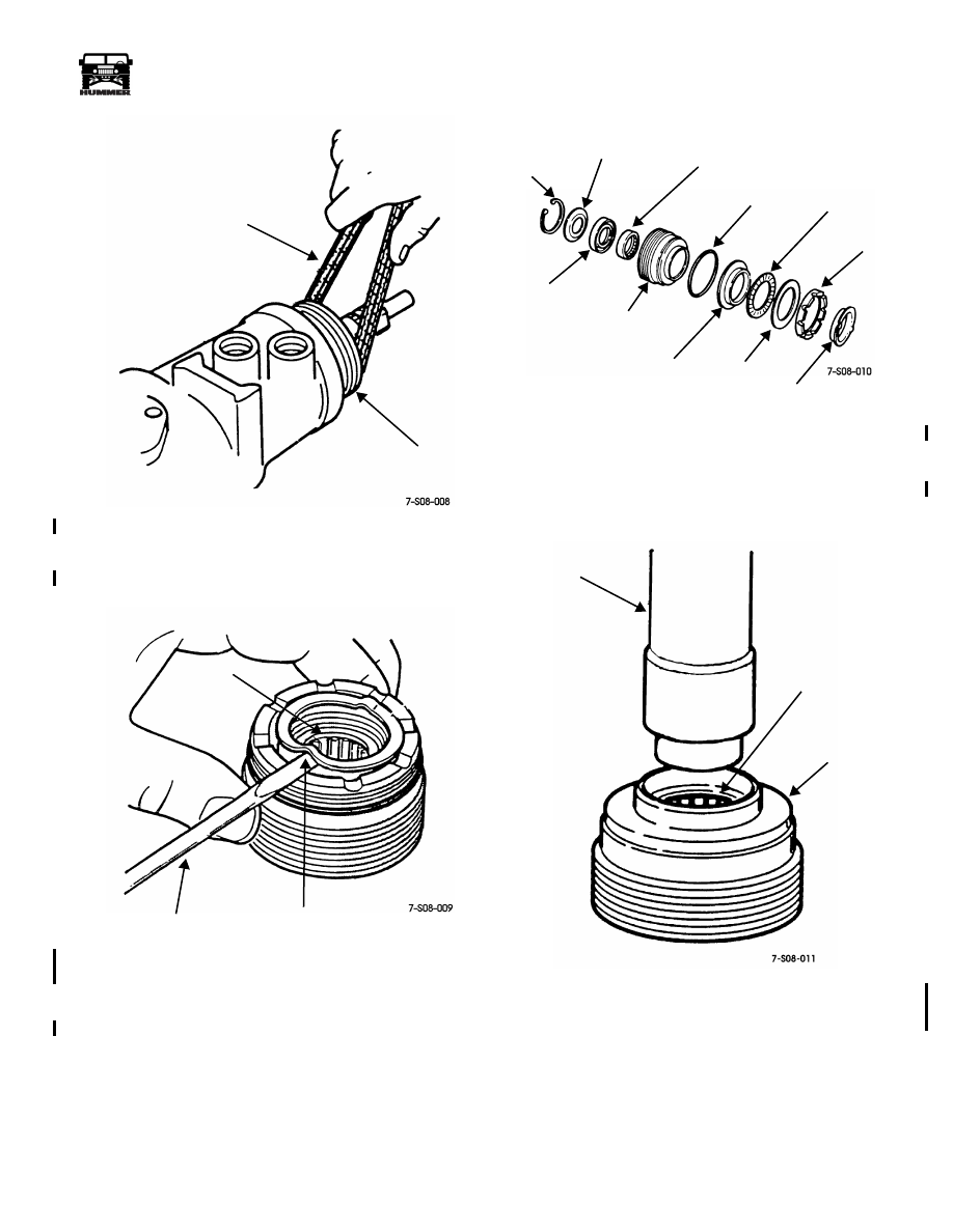
Adjuster Plug Removal and Disassembly
1.
Remove adjuster plug locknut with punch and hammer
(Figure 8-34).
Figure 8-34: Adjuster Plug Locknut Removal
2.
Remove adjuster plug from housing with spanner wrench
J–7624 (Figure 8-35).
PUNCH
RETAINING RING
SCREWDRIVER
RETAINING
END
O-RING
GEAR
RING
PLUG
HOUSING
PUNCH
ADJUSTER
PLUG
LOCKNUT
4-1-00
_________________________________________________________
Steering System 8-25
®
05745159
Figure 8-35: Adjuster Plug Removal
3.
Remove thrust bearing retainer by prying it up and out at
raised point on retainer (Figure 8-36).
Figure 8-36: Adjuster Plug Thrust Bearing
Retainer Removal
4.
Remove bearing spacer, thrust bearing and races, and O-
ring (Figure 8-37).
Figure 8-37: Adjuster Plug Components
5.
Remove stub shaft seal retainer.
6.
Remove dust seal and oil seal (Figure 8-38). Use tool
J–6221 to remove seals.
Figure 8-38: Stub Shaft Bearing Removal
7.
Remove stub shaft bearing with tool J–6221 (Figure 8-38).
SPANNER
ADJUSTER PLUG
TOOL
J–7624
SPACER
RAISED SECTION
OF RETAINER
SCREWDRIVER
SNAP
STUB SHAFT
STUB SHAFT
O-RING
INNER
THRUST
OUTER
RETAINER
ADJUSTER
STUB
SHAFT
BEARING
PLUG
RACE
BEARING
SPACER
RACE
SEAL
RING
OIL SEAL
DUST SEAL
TOOL J–6221
STUB
ADJUSTER
PLUG
SHAFT
BEARING
4-1-00

8-26
Steering System
__________________________________________________________
®
Rack Piston Removal and Disassembly
1.
Rotate stub shaft counterclockwise until rack piston is
even with seal groove in open end of housing. Do not
allow the rack piston to extend out of the housing. It only
needs to be about 1/4 inch from the end.
2.
Remove rack piston plug (Figure 8-39). Use a ratchet and
socket extension to remove the plug as shown.
Figure 8-39: Rack Piston Plug Removal
3.
Insert arbor tool J–21552 into rack piston (Figure 8-40).
Figure 8-40: Rack Piston Removal
4.
Hold arbor tool tightly in rack piston and turn stub shaft
counterclockwise to push rack piston out of housing. Then
remove rack piston, and arbor tool as assembly
(Figure 8-40).
5.
Remove wormshaft if it came out of stub shaft
(Figure 8-41).
Figure 8-41: Wormshaft Removal
6.
Remove thrust bearing and races from wormshaft.
7.
Remove teflon seal rings and backup O-rings from rack
piston (Figure 8-42).
Figure 8-42: Rack Piston Components
8.
Remove bolts attaching recirculating ball guide halves to
rack piston, remove guides, and remove bearings from
rack piston (Figure 8-41). A total of 24 bearings are used;
12 chrome and 12 black.
EXTENSION
PISTON
RATCHET
RACK
PISTON
PLUG
RACK PISTON
ARBOR TOOL
J–21552
ARBOR TOOL
RACK PISTON
WORMSHAFT
J–21552
TEFLON
RACK
BEARING
BALL GUIDES
BALL
O-RING
SEAL
GUIDE
CLAMP
RING
PISTON
BALLS
4-1-00
Нет комментариевНе стесняйтесь поделиться с нами вашим ценным мнением.
Текст