Hummer H1 (2002+). Manual — part 131
_________________________________________________________
Steering System 8-31
®
05745159
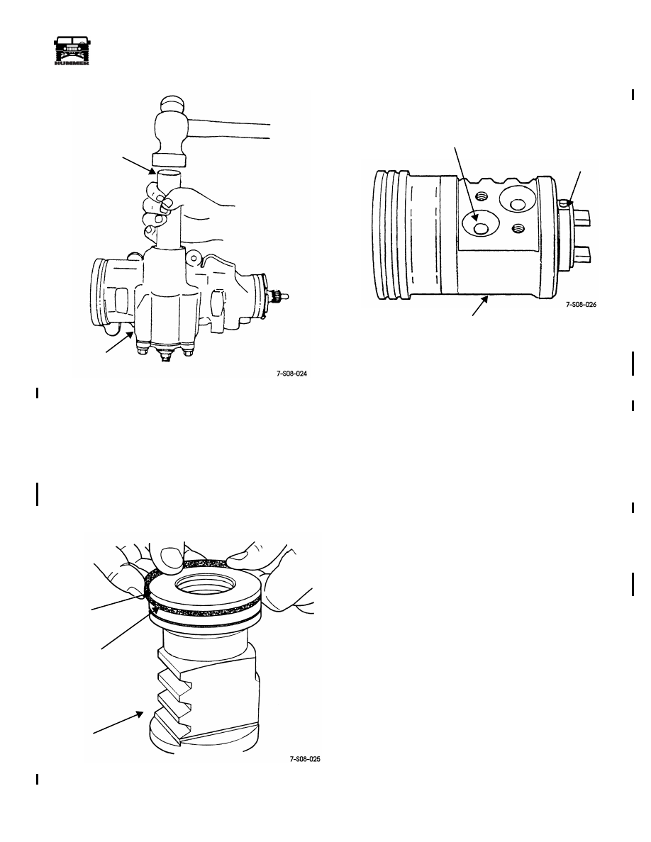
Figure 8-51: Pitman Shaft Seal Installation
Rack Piston Assembly
1.
Lubricate rack piston bore in gear housing and new O-ring
and seal ring with power steering fluid.
2.
Install new backup O-ring in rack piston seal groove.
3.
Install new teflon seal ring in groove
over
backup O-ring
(Figure 8-52).
Figure 8-52: Rack Piston Seal Ring Installation
4.
Install wormshaft in rack piston. Wormshaft flange should
be seated against piston as shown (Figure 8-53).
Figure 8-53: Rack Piston Loading Port
For Bearing Balls
5.
Align worm shaft spiral groove with indicated ball guide
circuit port in rack piston (Figure 8-53).
6.
Load recirculating bearing balls in rack piston and in ball
guides as follows:
a.
Lubricate bearing balls with power steering fluid.
b.
Turn wormshaft
counterclockwise
to load bearing
balls in rack piston.
c.
Load balls in rack piston through indicated ball guide
port (Figure 8-53).
d.
Load balls alternately. Start with chrome ball
followed by black ball until rack piston is full (piston
will only accommodate around 18 balls).
e.
Load remaining balls in ball guides. Use petroleum
jelly to hold balls and guide halves in place
(Figure 8-54).
f.
Verify that 12 black and 12 chrome balls were
installed in correct sequence.
g.
Assemble and install ball guides (with enclosed balls)
on rack piston and secure guides with clamp. Tighten
clamp bolts to 43 lb-ft (58 N•m) torque.
WARNING: The chrome recirculating balls are
slightly larger in diameter than the black coated balls.
This is required in order to generate and maintain
proper wormshaft preload. It is also why the balls must
be installed alternately. Incorrect installation, or failure
to load all 24 balls will result in loss of preload, bind,
and partial loss of steering control. Verify that the balls
are correctly loaded before proceeding.
INSTALLER
GEAR
TOOL
J–6219
HOUSING
TEFLON RING
NOTE: BACK-UP
UNDER SEAL RING
RACK PISTON
O-RING IS INSTALLED
LOAD BEARING BALLS
WORMSHAFT
RACK
PISTON
FLANGE
INTO THIS BALL GUIDE PORT
4-1-00

8-32
Steering System
__________________________________________________________
®
Figure 8-54: Assembling Remaining Bearing Balls
and Ball Guides
7.
Remove wormshaft and temporarily install arbor tool
J–21552 as follows:
a.
Insert arbor tool J–21552 into rack piston end plug
hole.
b.
Hold arbor tool firmly against wormshaft and turn
wormshaft
counterclockwise
. This allows wormshaft
to back out of piston as arbor tool enters and holds
recirculating balls in place.
8.
Set rack piston aside temporarily for later installation. Do
not allow the arbor tool to slip out of the piston. If this
occurs, it will be necessary to disassemble and reload the
bearing balls.
Valve Body-Stub Shaft-Wormshaft Assembly
1.
Lubricate valve body spool, O-rings, and seal rings with
power steering fluid.
2.
Install new backup O-rings in valve body grooves.
3.
Install new teflon coated seal rings in valve body grooves.
Note that the seal rings are installed on top of (over) the
backup O-rings (Figure 8-55).
Figure 8-55: Valve Body Seal Ring Installation
4.
Install new O-ring on valve spool.
5.
Install spool in valve body with a turning motion
(Figure 8-59). Note that O-ring end of spool faces out.
CAUTION:
Do not force the spool into the valve. This could
score the spool and valve body resulting in steering problems
after installation. Install the spool with a push and turn motion
only.
Figure 8-56: Valve Body Seal Ring Installation
BEARING
BALL
PETROLEUM
JELLY
BALLS
GUIDE
HALVES
TEFLON COATED
SEAL RING
(OVER O-RING)
VALVE BODY
SPOOL
4-1-00

_________________________________________________________
Steering System 8-33
®
05745159
6.
Install stub shaft in valve body as follows:
a. Insert stub shaft into valve body.
b. Leave approximately 1/4 inch (6 mm) space between
stub shaft cap and valve body for access to pin
(Figure 8-57).
c. Align and engage stub shaft pin in valve spool pin bore
(Figure 8-57).
d. Align notch in stub shaft cap with pin in valve body
(Figure 8-58). Then fully seat stub shaft in valve body.
Verify that valve body pin is seated in cap notch before
proceeding.
Figure 8-57: Aligning Stub Shaft Pin and Valve Spool
Pin Bore
Figure 8-58: Aligning and Seating Stub Shaft
In Valve Body
7.
Lubricate wormshaft thrust bearings and races with
petroleum jelly to hold them in place. Then install first
race followed by the bearing and remaining race
(Figure 8-59).
CAUTION:
The thrust bearing races both have a concave
shape. Be sure the concave side is toward the wormshaft flange
as shown. The races will not maintain proper preload on the
bearing otherwise.
STUB
6mm
PIN BORE
IN SPOOL
SHAFT
PIN
(1/4 ")
NOTCH IN
VALVE
STUB SHAFT CUP
BODY
PIN
(SEAT IN
CAP
NOTCH)
4-1-00

8-34
Steering System
__________________________________________________________
®
Figure 8-59: Aligning and Seating Stub Shaft In
Valve Body
8.
Install O-ring on stub shaft cap (Figure 8-63).
9.
Align slot in valve body with pin in wormshaft flange and
insert wormshaft into valve body (Figure 8-63). Be sure
wormshaft flange is fully seated in stub shaft.
10. Set assembly aside for later installation.
Figure 8-60: Wormshaft and Valve Body/Stub Shaft
Assembly
Adjuster Plug Assembly
1.
Position new stub shaft bearing on installer tool J–6221.
Position bearing so ID number is toward installer tool.
This will minimize any chance of damaging the bearing
during installation.
2.
Install stub shaft bearing in adjuster plug with tool J–6221
(Figure 8-61). Place adjuster plug on wood block as
shown.
Figure 8-61: Installing Stub Shaft Bearing and Seals
In Adjuster Plug
3.
Install stub shaft oil seal and dust seal in adjuster plug with
tool J–6221. Then install snap ring to secure seals and
bearing (Figure 8-62).
4.
Assemble and install thrust bearing and races in adjuster
plug (Figure 8-62). Be sure races are installed as shown
(Figure 8-62).
5.
Install spacer and retainer in adjuster plug (Figure 8-62).
6.
Seat retainer in adjuster plug with pin punch (Figure 8-63).
7.
Install O-ring on adjuster plug (Figure 8-63).
THRUST
CONCAVE (ANGLED) SIDE OF RACES
MUST BE TOWARD WORMSHAFT FLANGE
BEARING
THRUST BEARING
ALIGN PIN
VALVE BODY/
O-RING
WORMSHAFT
MAKE SURE ANGLE OF
THRUST RACES ARE AS SHOWN
AND RACES
STUB SHAFT
ASSEMBLY
AND SLOT
TOOL J–6221
ADJUSTER
WOOD
STUB SHAFT
BLOCK
PLUG
BEARING
4-1-00
Нет комментариевНе стесняйтесь поделиться с нами вашим ценным мнением.
Текст