Hummer H1 (2002+). Manual — part 192
_____________________
Heating/Ventilation/Air Conditioning (HVAC) 11-47
®
05745159
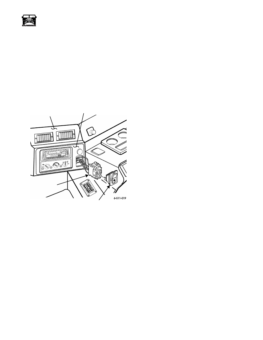
AUXILIARY BLOWER SWITCH REPLACEMENT
Removal
1.
Pull front console away from dashboard.
2.
Depress tabs on blower switch and push through faceplate.
3.
Remove connector from back of blower switch
(Figure 11-88).
Installation
1.
Secure connector to blower switch and check operation
(Figure 11-88).
2.
Install front console.
3.
Push blower switch into opening in faceplate.
Figure 11-88: Blower Switch Replacement
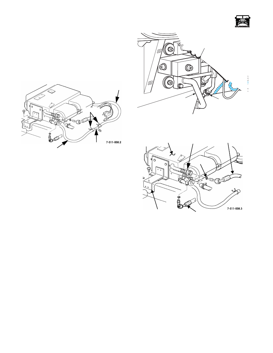
AUXILIARY HEATER HOSE REPLACEMENT
NOTE: Heater hose replacement is the same for both heater
hoses.
NOTE: Production heater hose will have full underbody
length of foil back insulation sleeve. Make sure replacement
hose also has this protection.
Removal
1.
Drain cooling system (Section 4).
2.
Remove air cleaner induction tube (Section 3).
3.
Select heater hose to replace, loosen hose clamps, and
remove heater hose from hose splice.
4.
Remove two P-clamps from underbody securing auxiliary
hoses.
5.
Remove front and rear consoles.
6.
Remove screw clamp securing heater hose to heater core
port on auxiliary unit (Figure 11-87).
7.
Pull heater hose through tunnel grommet.
8.
Remove heater hose.
Installation
1.
Attach one hose end to auxiliary unit heater core port and
secure with clamp (Figure 11-87).
2.
Route hose through grommet to engine area.
3.
Connect hose to hose splice and secure with clamp.
4.
Install two P-clamps to underbody securing installed hose
to existing hoses.
5.
Fill cooling system (Section 4).
6.
Install air cleaner induction tube (Section 3).
7.
Pressure test cooling system and check for leaks.
8.
Install front and rear consoles.
9.
Start engine and run until engine warms up.
10. Check heating units for proper operation.
BLOWER
FRONT CONSOLE
SWITCH
FACEPLATE
CONNECTOR
11-48
Heating/Ventilation/Air Conditioning (HVAC)
______________________
®
AUXILIARY A/C DRAIN TUBE(S)
REPLACEMENT
Removal
1.
Remove rear console.
2.
Remove clamps from drain tube section being replaced
(Figure 11-89).
3.
Remove drain tube.
Figure 11-89: Auxiliary A/C Drain Tube
Replacement
Installation
1.
Install drain tube section and secure with clamps
(Figure 11-89).
2.
Install rear console.
AUXILIARY HIGH-PRESSURE HOSE
REPLACEMENT
NOTE: Production hoses have a full underbody length of foil-
backed heat-resistant sleeving. Replacement hoses should have
the same level of thermal protection.
Removal
1.
Discharge air conditioning system.
2.
Remove air cleaner assembly and air induction tube
(Section 3).
3.
Remove rear console.
4.
Remove front console.
5.
Using two wrenches to equalize support, remove auxiliary
high-pressure hose from expansion valve manifold.
Remove and discard O-ring (Figure 11-90).
6.
Using two wrenches for equalized support, remove
auxiliary high pressure hose from auxiliary expansion
valve. Remove and discard O-ring (Figure 11-91).
7.
Remove two P-clamps securing hose to underbody.
8.
From under the vehicle pull high-pressure hose through
grommet.
Figure 11-90:
.
Auxiliary High-Pressure Hose
Connection, Front
Figure 11-91: Auxiliary High-Pressure Hose
Connection, Rear
Installation
1.
Route expansion valve end of hose through grommet to
auxiliary unit.
2.
Lubricate and position O-ring on high pressure hose and
hand thread hose fitting onto expansion valve. Using two
wrenches for equalized support, tighten to 11-13 lb-ft (15-
18 N•m) (Figure 11-91).
3.
Route other end of hose to expansion valve manifold
(Figure 11-90).
4.
Lubricate and position O-ring on hose and secure to high
expansion valve manifold. Using two wrenches for
equalized support, tighten to 11-13 lb-ft (15-18 N•m).
5.
Install two P-clamps to secure hoses to underbody.
6.
Install front and rear consoles.
7.
Evacuate, charge, and leak test system.
8.
Start engine and check A/C operation.
DRAIN
TEE
DRAIN TUBE
TUBE
CLAMPS
7-S11-063
HIGH PRESSURE HOSE
CONNECTION (AUX.)
EXPANSION VALVE
MANIFOLD
HEATER TUBE
AUXILIARY
O-RING
LOW PRESSURE
HIGH
MOUNTING BRACKET
UNIT
EXPANSION
VALVE
HOSE
PRESSURE
A/C HOSE
_____________________
Heating/Ventilation/Air Conditioning (HVAC) 11-49
®
05745159
AUXILIARY LOW-PRESSURE HOSE
REPLACEMENT
Removal
1.
Discharge air conditioning system.
2.
Remove air cleaner assembly and air induction tube
(Section 3).
3.
Using two wrenches for equalized support, remove
auxiliary low-pressure hose from low-pressure hose
fitting. Remove and discard O-ring (Figure 11-90).
4.
Remove two P-clamps securing hoses to underbody.
5.
Remove front and rear consoles.
6.
Remove prestite tape from low-pressure hose. Using two
wrenches for equalized support, remove hose from
auxiliary unit. Remove and discard O-ring (Figure 11-91).
7.
From under the vehicle, pull low-pressure hose through
grommet.
CAUTION: To avoid potential thread or fitting damage, hand
start connections before using wrenches.
Installation
1.
Route evaporator end of hose through grommet to auxil-
iary unit.
2.
Lubricate and position O-ring on hose and secure to
auxiliary unit. Using two wrenches for equalized support,
tighten to 21-27 lb-ft (29-37 N•m) (Figure 11-91).
3.
Route other end of low-pressure hose to under hood low
pressure fittings.
4.
Lubricate and position O-ring and secure auxiliary low
pressure hose to existing low pressure hose fitting. Using
two wrenches for equalized support, tighten to 24-28 lb-ft
(33-38 N•m) (Figure 11-90).
5.
Install two P-clamps to secure hoses to underbody.
6.
Install front and rear consoles.
7.
Evacuate, charge, and leak test system.
8.
Start engine and check A/C operation.
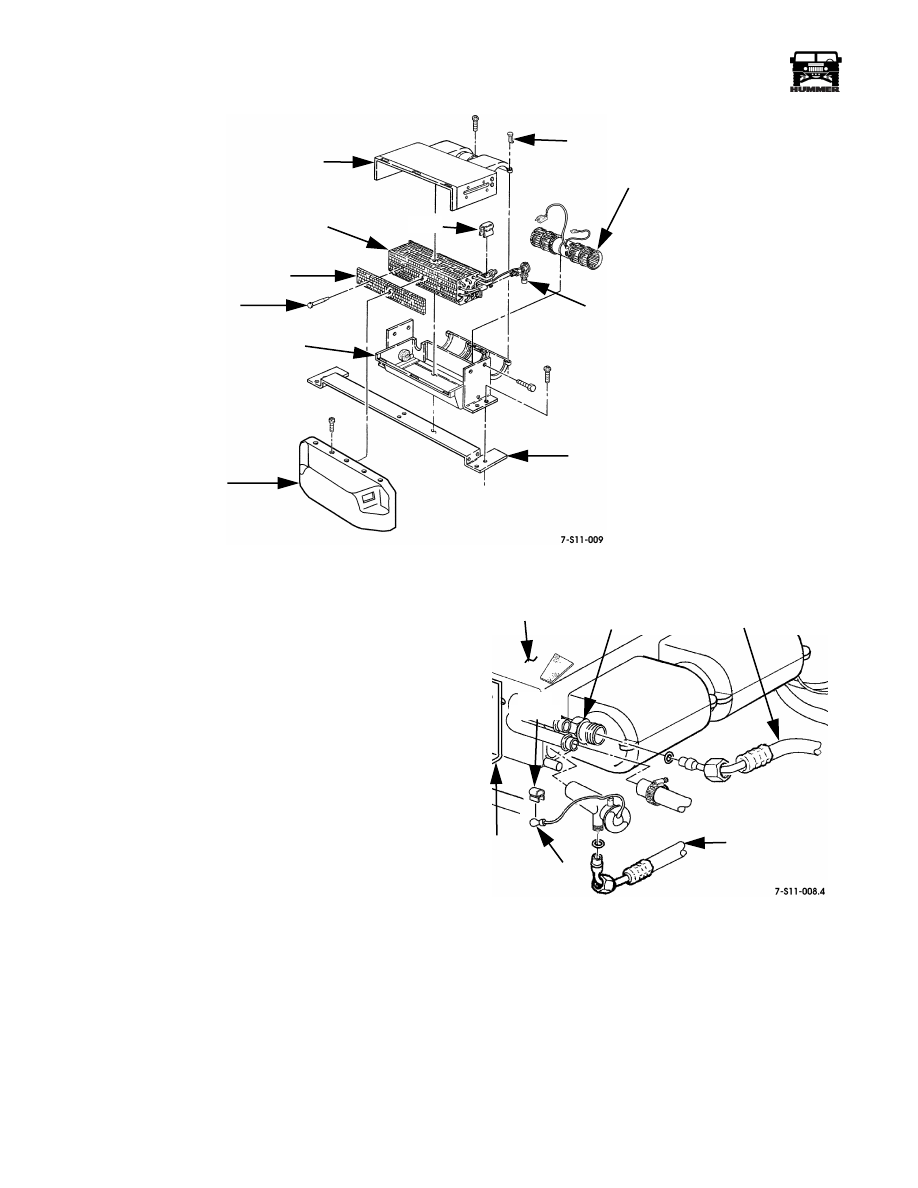
AUXILIARY EVAPORATOR/HEATER CORE
REPLACEMENT
Removal
1.
Remove auxiliary unit from vehicle.
2.
Remove four screws and plenum from housing.
3.
With auxiliary unit on bench, remove six plastic locking
pins securing unit housing halves together (Figure 11-92).
4.
Remove four screws from blower motor support.
5.
Remove four screws securing side brackets to upper
housing half.
6.
Separate housing halves.
7.
Remove blower motor assembly from bottom housing.
8.
Remove evaporator/heater core assembly from bottom
housing.
9.
Remove plastic stick pins and mesh filter from evaporator/
heater core assembly.
NOTE: If expansion valve is to be reused, remove from evap-
orator/heater core assembly and install on replacement unit.
Installation
1.
Install mesh filter on evaporator/heater core assembly with
plastic stick pins (Figure 11-92).
2.
Install evaporator/heater core assembly in bottom housing.
3.
Install blower motor assembly in bottom housing.
4.
Install upper housing to lower housing with six plastic
locking pins, four blower motor support screws, and four
screws securing side brackets to upper housing.
5.
Install plenum on housing with four screws.
6.
Install auxiliary unit into vehicle.
7.
Evacuate, charge, and leak test A/C and heating system.
AUXILIARY BLOWER MOTOR REPLACEMENT
Removal
1.
Disconnect auxiliary unit mounting hardware and tilt unit
up to gain access to blower motor support screws.
2.
Remove support screws and screws securing side brackets
to upper housing half.
3.
Separate housing halves and remove blower motor
assembly from bottom housing.
Installation
1.
Installation is the reverse of the removal procedure.
11-50
Heating/Ventilation/Air Conditioning (HVAC)
______________________
®
Figure 11-92: Auxiliary Air Conditioning Components
AUXILIARY EXPANSION VALVE
REPLACEMENT
Removal
1.
Discharge air conditioning system.
2.
Remove rear console.
3.
Remove prestite tape and bulb clamp.
4.
Using two wrenches for equalized support, remove high-
pressure hose from expansion valve. Remove O-ring from
hose and discard O-ring (Figure 11-93).
5.
Using two wrenches for equalized support, remove
expansion valve from auxiliary unit. Remove and discard
O-ring (Figure 11-86).
Installation
1.
Install O-ring and expansion valve on auxiliary unit. Using
two wrenches for equalized support, tighten to 15-20 lb-ft
(20-27 N•m) (Figure 11-86).
2.
Position O-ring onto high pressure hose and hand-thread
hose fitting onto the expansion valve. Using two wrenches
for equalized support, tighten to 11-13 lb-ft (15-17 N•m)
(Figure 11-93).
3.
Install prestite tape and bulb clamp.
4.
Evacuate, charge, and leak test system.
5.
Install rear console.
6.
Start engine and check operation of auxiliary unit.
Figure 11-93: Expansion Valve
Removal/Installation
PLENUM
TUNNEL SUPPORT BRACKET
EXPANSION VALVE
BLOWER MOTOR ASSEMBLY
PLASTIC LOCKING PIN
TOP HOUSING
EVAPORATOR/HEATER
CORE ASSEMBLY
MESH FILTER
PLASTIC PIN
BOTTOM HOUSING
CLIP
AUXILIARY
LOW PRESSURE A/C HOSE
MOUNTING
UNIT
BULB
HIGH PRESSURE
HOSE
EXPANSION
VALVE
BRACKET
BULB
CLAMP
Нет комментариевНе стесняйтесь поделиться с нами вашим ценным мнением.
Текст