Hummer H1 (2002+). Manual — part 191

_____________________
Heating/Ventilation/Air Conditioning (HVAC) 11-43
®
05745159
EVAPORATOR
Replacement
1.
Remove HVAC unit from vehicle (refer to HVAC unit
replacement).
2.
Remove heater core from main unit (refer to heater core
replacement).
3.
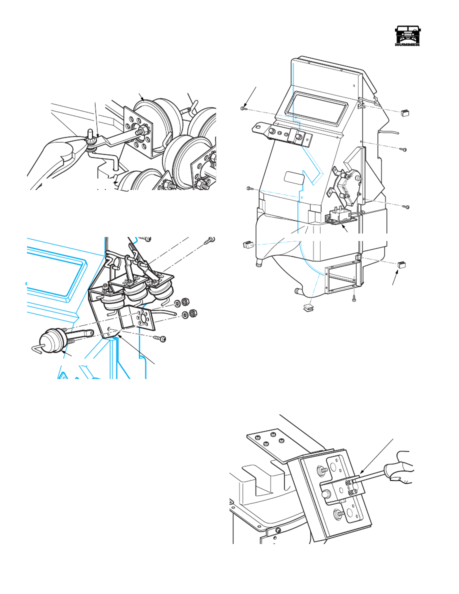
Remove lower support bracket from HVAC case
(Figure 11-72).
Figure 11-72: Lower Support Bracket Removal
4.
Disconnect vacuum harness from vacuum motors. Motors
are color coded to vacuum tubing (Figure 11-72).
Figure 11-73: Vacuum Door Motor Harness
5.
Remove air intake housing from main unit by removing
attaching screws at blower housing (Figure 11-75) and
bracket at front of unit (Figure 11-74).
Figure 11-74: Air Intake Box Front Bracket Removal
Figure 11-75: Lower Blower Housing Hardware
Removal
6.
Remove face duct outlet plenum (Figure 11-76).
Figure 11-76: Face Duct Outlet Plenum
7.
Remove floor door travel limiting rivet by drilling head,
note the side of the rivet the door is resting on
(Figure 11-77).
NOTE: Place a reference mark on the case to ensure that the
rivet is placed in the same location during reassembly that it
was removed from (Figure 11-77).
Figure 11-77: Drilling Door Travel Limiting Rivet
7-S11-042
BRN
BLU
YEL
GRY
ORG
BLK
WHT
RED
VACUUM DOOR MOTOR HARNESS
7-S11-051
7-S11-052
7-S11-043
FACE OUTLET PLENUM
7-S11-059
7
REFERENCE MARK
DEFROST OUTLET
FLOOR OUTLET
7-S11-041
11-44
Heating/Ventilation/Air Conditioning (HVAC)
______________________
®
8.
Remove arm retaining push clip, arm and 2 washers from
the floor door and defrost door (Figure 11-78).
Figure 11-78: Push Clip Removal
9.
Remove defrost motor from the bracket, note position of
mounting studs in mounting plate (Figure 11-79).
Figure 11-79: Vacuum Door Motor Mounting Plate
10. Remove arm retaining push nuts and washers from
remaining vacuum motors.
11. Remove screws securing vacuum motor mounting plate to
main HVAC unit, and remove mounting plate. If the floor
door travel limiting rivet was not removed, the door arm
will prevent removal of the mounting plate by not aligning
with the elongated slot (Figure 11-79).
12. Remove screws securing case halves together. Do not
attempt to separate case at this time (Figure 11-80).
13. Remove screws securing thermostatic cycling switch to
HVAC unit case (Figure 11-80).
CAUTION: Do not attempt to pull the switch out of the case,
the capillary tube is secured to the evaporator.
14. Using a utility knife, carefully cut through the sealer
between the two case halves. Use caution to prevent
cutting the case.
Figure 11-80: Case Half Hardware Removal
15. Using a putty knife or scraper, carefully spread apart the
entire case seam.
16. Separate case halves. Note that the thermostatic cycling
switch must stay with the case half containing the evaporator.
17. Remove permagum tape from around liquid and vapor
tubes, discard.
18. Remove expansion valve from the passthrough plate,
discard gasket (Figure 11-81).
Figure 11-81: Expansion Valve Removal
PUSH CLIP
DEFROST DOOR MOTOR
FLOOR DOOR MOTOR
7-S11-040
7-S11-046
DEFROST DOOR MOTOR
VACUUM DOOR
MOUNTING PLATE
7-S11-048
SCREW
S-CLIP
THERMOSTATIC CYCLING SWITCH
EXPANSION VALVE
7-S11-044

_____________________
Heating/Ventilation/Air Conditioning (HVAC) 11-45
®
05745159
19. Remove screws securing passthrough plate support
bracket to the main unit (Figure 1-82).
Figure 1-82: Passthrough Plate Support Removal
20. Remove bolt securing passthrough plate to the evaporator
manifold connection, remove plate and support bracket.
21. Remove evaporator from unit (Figure 1-83).
22. Carefully remove capillary tube from evaporator, noting
positioning in the evaporator fins (Figure 1-83).
Figure 1-83: Evaporator Removal
23. Disconnect evaporator extension tubes at the O-ring
fittings (Figure 1-84). Discard the O-rings.
Figure 1-84: Evaporator Extension Tubes Removal
Installation
1.
Obtain new evaporator. Ensure that any foam tape found on
the previously removed unit is duplicated on the replacement.
2.
Install extension tubes onto new evaporator using new o-
rings lubricated with refrigerant oil.
3.
Install evaporator into the case half the previous
evaporator was removed from
4.
Position thermostat capillary tube in the same location it was
removed from on the original evaporator. I will be necessary
to hot glue the tube near the exit hole (Figure 1-83).
5.
Install second half of HVAC unit, ensuring that the edges
of the case halves engage the S clips around the seam.
6.
Install screws securing the two halves together.
7.
Install screws securing cycling switch to the side of the
HVAC case.
8.
Using neutral cure silicone sealer, seal entire parameter of seam.
9.
Install the passthrough plate onto the main unit and
evaporator. Install bolt securing evaporator extension tubes
to the passthrough plate. Use a new sealing washer between
the passthrough plate and the evaporator extension tubes.
NOTE:
It may be necessary to trim the middle from the gasket
as received. The normal span of the gasket will not fit the evap-
orator extension tube span.
10. Install expansion valve with a new sealing washer and
torque to 100 in lbs.
11. Install Vacuum motor bracket onto main unit
12. Install defrost door motor onto mounting plate.
13. Connect all vacuum motors to their perspective door arms
using washers and new push clips.
14. Install a new door travel limiting rivet into case, placing the
door on the side of the rivet it was originally resting on.
15. Install face duct plenum.
16. Install air intake assembly onto the main case.
17. Install lower support bracket.
18. Install heater core and retaining brackets, using new
sealing washers on the heater core tubes. Torque heater
manifold to 32 in lbs.
19. Install vacuum harness onto vacuum motors.
20. Install unit into vehicle (refer to HVAC unit removal and
installation).
21. Fill the cooling system.
22. Evacuate A/C system for minimum of 45 minutes, with a
10 minute hold time for leak check. Recharge with 3 lbs
2oz , adding same amount of oil that was drained from the
original evaporator.
Cycling Switch Replacement
Refer to evaporator replacement.
Air Intake Assembly Replacement
Refer to evaporator replacement.
7-S11-050
7-S11-060
THERMOSTATIC CYCLING SWITCH
HOT GLUE
7-S11-045
EXTENSION TUBES
EVAPORATOR
7-S11-045
11-46
Heating/Ventilation/Air Conditioning (HVAC)
______________________
®
REAR CONSOLE REPLACEMENT
Removal
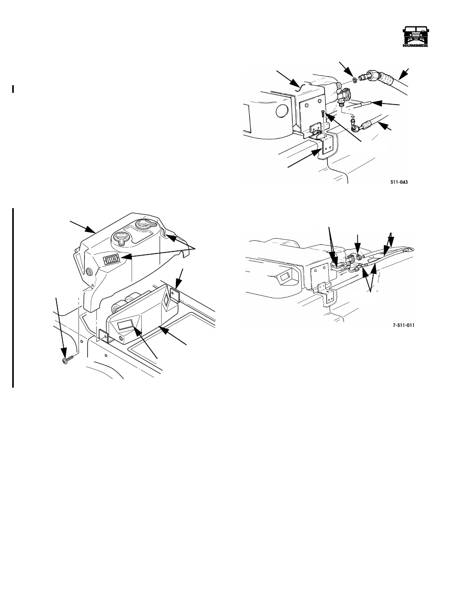
1.
Remove two screw/washers securing rear console to side
brackets (Figure 1-85).
2.
Push console rearward so that the vents are clear from the
plenum cutouts.
3.
Remove rear console.
Installation
1.
Position rear console over the auxiliary HVAC unit so that
the console vents line up with the plenum cutouts.
2.
Push console forward until vents fit into plenum.
3.
Secure rear console to side brackets with screw/washers
(Figure 1-85).
Figure 1-85: Rear Console Installation
AUXILIARY AIR CONDITIONING/HEATING
UNIT REPLACEMENT
Removal
1.
Discharge air conditioning system.
2.
Remove rear console (Section 10).
3.
Remove heater hoses from auxiliary unit heater core ports
(Figure 1-87).
4.
Remove pressure hoses from auxiliary unit.
5.
Remove drain tubes from auxiliary unit (Figure 1-87).
Figure 1-86: Auxiliary A/C Components
Figure 1-87: Auxiliary Heater Hose Routing
6.
Remove screws securing side brackets to tunnel mounting
bracket.
7.
Remove auxiliary unit from vehicle.
Installation
1.
Install auxiliary unit in vehicle and secure side brackets to
tunnel mounting bracket with screws (Figure 1-86).
2.
Install drain tubes on auxiliary unit (Figure 1-87).
3.
Install pressure hoses on auxiliary unit.
4.
Wrap low pressure fitting with prestite tape.
5.
Secure heater hoses to heater core ports on auxiliary unit
with worm gear clamps. Remove hose pinch pliers.
6.
Evacuate, charge, and leak test air conditioning system.
7.
Check engine coolant level and add coolant as necessary.
8.
Start engine and operate auxiliary and front air
conditioning system to check for proper operation.
9.
Check coolant connections for leakage; repair if
necessary.
10. Stop engine, recheck coolant level, and add coolant if
necessary.
11. Install rear console (Section 10).
00-S11-006
REAR
VENTS
SIDE
BRACKET
PLENUM
SCREW/WASHER
CONSOLE
PLENUM CUTOUT
MOUNTING
SMALL
LARGE
O-RING
AUXILIARY UNIT
BRACKET
SELF-TAPPING
SCREW
A/C HOSE
A/C HOSE
DRAIN
TUBES
HEATER
CORE
PORTS
CLAMP
HEATER
HOSES
DRAIN TUBES
AND TEE
4-1-00
Нет комментариевНе стесняйтесь поделиться с нами вашим ценным мнением.
Текст