Hummer H1 (2002+). Manual — part 44
___________________________________________
Fuel, Emissions, and Exhaust 3-37
®
5745159
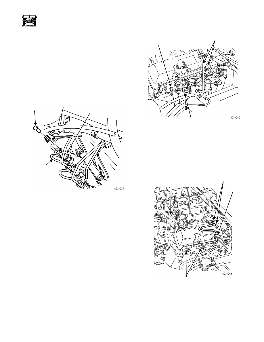
Fuel Injector Replacement
Removal
1.
If removing rear injector, remove console and engine
cover. Remove fuel return hose and cap from injector
(Figure 3-52).
2.
Disconnect fuel return hoses from necessary injector
(Figure 3-53).
3.
Remove clamp, and fuel injector line bracket and clamp.
4.
Disconnect fuel line at injector (Figure 3-53).
5.
Using socket J–29873, remove injector and gasket from
cylinder head.
Figure 3-52: Rear Injector Fuel Cap Location
Installation
1.
Apply antiseize compound to threads of new injector.
2.
Install gasket and fuel injector in cylinder head. Tighten
injector to 44-60 lb-ft (60-81 N•m).
3.
Connect fuel line to injector. Tighten fuel line to 20 lb-ft
(27 N•m).
4.
Install injection line bracket and clamp.
5.
Install fuel drain hose and cap.
6.
Connect drain hoses to injectors.
7.
Start engine and bleed injectors.
8.
Install console and cover.
Figure 3-53: Fuel Injector and Gasket Removal/
Installation
Injection Line Replacement
Removal
1.
Remove injection pump boot.
2.
Disconnect injection lines at injectors (Figure 3-54).
Figure 3-54: Fuel Injection Line Routing (Typical)
3.
Remove injection line brackets.
NOTE: Tag fuel injection lines by cylinder number for instal-
lation reference.
4.
Disconnect injection lines at pump.
5.
Remove fuel line clamps.
CAP
REAR INJECTOR
FUEL RETURN HOSE
GASKET
INJECTOR LINES
INJECTOR
FUEL INJECTOR
INJECTION
PUMP
INJECTOR LINES
CLAMP
FUEL INJECTORS
3-38
Fuel, Emissions, and Exhaust
___________________________________________
®
Installation
1.
Install clamps on injection lines (Figure 3-54).
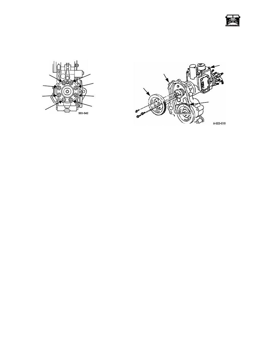
2.
Connect injection lines to pump (Figure 3-55).
3.
Connect lines to injectors.
Figure 3-55: Fuel Injection Pump Line Connection
4.
Tighten injection line nuts to 20 lb-ft (27 N•m).
5.
Install injection line brackets.
6.
Install intake manifold.
7.
Start and run engine.
8.
Bleed all injectors.
Fuel Injection Pump
Removal
1.
Remove engine oil filler neck and cap.
2.
Disconnect intake hoses at intake manifold.
3.
Disconnect fuel lines at injectors. Then remove fuel line
clamps.
4.
Remove clip attaching accelerator cable to pump lever.
5.
Disconnect all solenoid and harness wires at injection
pump.
6.
Remove throttle position sensor.
7.
Disconnect fuel hoses at injection pump.
8.
Disconnect injector fuel lines at pump. Tag lines for
assembly reference if desired.
9.
Remove throttle return spring from throttle shaft lever.
NOTE: Rotate engine to gain access to driven gear-to-injec-
tion pump capscrews through oil filler tube opening
10. Remove bolts attaching pump driven gear.
11. Remove nuts and washers, attaching pump and gasket to
timing gear cover.
12. Remove pump (Figure 3-56).
Service
The turbo diesel electronic injection pump is not serviceable.
Only the pump solenoids, sensors, gaskets, and drive gears are
serviceable. The pump should be replaced as an assembly if an
internal fault occurs.
Figure 3-56: Fuel Injection Pump
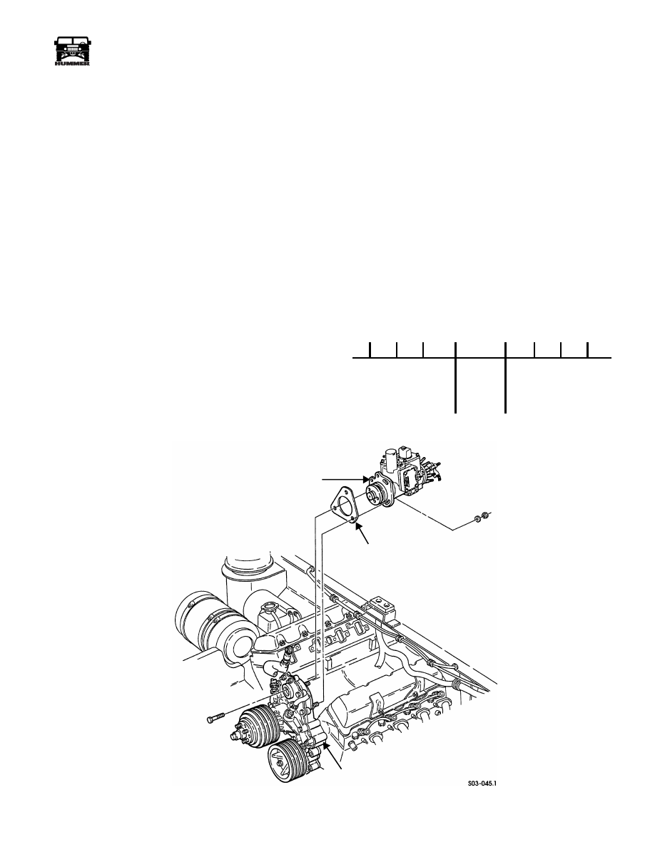
Installation
1.
Install gasket and fuel injection pump on timing gear cover
(Figure 3-57)
2.
Align pin on pump drive shaft with elongated hole in
pump driven gear.
3.
Align timing marks on injection pump and front cover.
4.
Tighten injection pump attaching nuts.
5.
Align and install pump driven gear. Tighten gear attaching
bolts to 13-20 lb-ft (18-27 N•m).
6.
Install hose adapter on injection pump if equipped.
7.
Install accelerator cable and bracket.
8.
Connect throttle return spring to throttle shaft lever and
accelerator cable mounting bracket.
9.
Connect fuel line to pump.
10. Install TPS.
11. Connect fuel lines to injectors.
12. Install injector line clamps and brackets.
13. Install engine oil filler tube.
14. Install fuel injector lines.
15. Install fast idle solenoid and mounting bracket, if equipped.
16. Adjust accelerator linkage on NA diesel models.
17. Connect fuel return hose.
18. Connect solenoid and sensor wires.
19. Reprogram TDC offset.
CYL. NO. 5
CYL. NO. 6
CYL. NO. 2
CYL. NO. 7
CYL. NO. 8
CYL. NO. 1
CYL. NO. 3
CYL. NO. 4
PUMP
DRIVEN
GEAR
FRONT
COVER
INJECTION
PUMP
PUMP
DRIVE
GEAR
___________________________________________
Fuel, Emissions, and Exhaust 3-39
®
5745159
Reprogramming TDC Offset
TDC offset must be reprogrammed whenever the PCM, front
cover, timing gears, timing chain, crankshaft position sensor,
or other components affecting timing are replaced. The proce-
dure for reprogramming TDC offset is as follows:
1.
Verify that vehicle batteries are fully charged.
2.
Start and run engine at curb idle speed
3.
Continue running engine at curb idle speed until coolant
reaches normal operating temperature.
4.
Connect Tech 1 scan tool to data link/diagnostic
connector.
5.
Select FO: OUTPUT TESTS from Miscellaneous Tests
menu.
6.
Select FO: INJ PUMP.
7.
Select TDC OFFSET LEARN>.
8.
Press Up Arrow key and PCM will learn engine top dead
center offset value. This requires approximately 20
seconds.
9.
Correct learned TDC offset value should be between
minus 0.25 and minus 0.75. If value is not within specified
range, loosen injection pump and rotate it to correct value
as follows:
NOTE: The engines should be off before the injection pump is
loosened and adjusted.
• If value is between plus 1.0 and minus 0.25, rotate pump
toward driver side to achieve specified value.
• If value is between minus 0.75 and minus 2.0, rotate
pump toward passenger to achieve specified value.
NOTE: 1 mm pump movement in either direction results in
approximately 2 degrees change.
Figure 3-57: Injection Pump Removal/Installation
WHEN THE TIMING
IS IN THIS REGION,
ROTATE PUMP TOWARD
DRIVER SIDE TO
WHEN THE TIMING
IS IN THIS REGION,
ROTATE PUMP TOWARD
PASSENGER SIDE TO
ACHIEVE TARGET ZONE.
ACHIEVE TARGET ZONE
TARGET
ZONE
+1.0
+.5
0
-.25
-.75
-1.0 -1.5
-2.0
FUEL
GASKET
TIMING GEAR COVER
INJECTION
PUMP
3-40
Fuel, Emissions, and Exhaust
___________________________________________
®
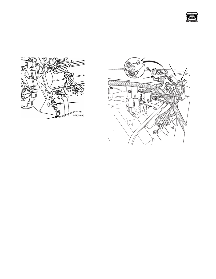
ENGINE TEMPERATURE SENDER
REPLACEMENT
1.
Remove nut, lockwasher, lead, and sender from engine
(Figure 3-58).
2.
Apply teflon sealant to sender threads, and install sender,
lead, lockwasher, and nut on engine (Figure 3-58).
Figure 3-58: Engine Temperature Sender
GLOW PLUG RELAY/CONTROLLER
REPLACEMENT
1.
Disconnect battery ground cable.
2.
Remove console and engine cover.
3.
Disconnect power cable at relay/controller (Figure 3-59)
.
Figure 3-59: Glow Plug Relay/Controller Location
4.
Disengage three connectors from glow plug controller.
5.
Remove retaining bolt and remove relay.
6.
Position relay/controller on bracket and install attaching
hardware.
7.
Engage connectors in relay/controller.
8.
Connect power cable to relay/controller stud.
9.
Install engine cover and console.
10. Connect battery ground cable.
SENSOR AND SWITCH SERVICE
The sensors and switches on turbo diesel engines are service-
able parts.
The boost pressure switch is on the passenger side valve cover.
The coolant temperature switch is in the water crossover.
The oil pressure switch is in the valley between the heads. The
MAP and air temperature sensors are at the passenger side of
the intake manifold.
SENDER
SENDER
WIRE
00-S12-010
CONTROLLER
LOCK PIN
POWER
CABLE
CONNECTOR
BOLT
Нет комментариевНе стесняйтесь поделиться с нами вашим ценным мнением.
Текст