Hummer H1 (2002+). Manual — part 150
________________________________________
Axles, Suspension, and Frame 9-61
®
05745159
Installation
1.
Position left and right crossmember mounting brackets on
crossmember (Figure 9-145).
2.
Install crossmember and mounting brackets on frame rails
with four washers, bolts, washers, and locknuts. Do not
tighten locknuts.
3.
Install left and right mounting brackets on crossmember
with six washers, bolts, washers, and locknuts. Tighten
locknuts to 90 lb-ft (122 N•m).
4.
Tighten mounting bracket-to-frame rail locknuts to 261 lb-
ft (354 N•m).
5.
Secure harness to crossmember with clamp and bolt.
6.
Install four washers, bolts, washers, locknuts, and two
splash shield brackets on frame rails. Tighten locknuts to
90 lb-ft (122 N•m) (Figure 9-144).
7.
Secure front crossmember to support bracket with two
washers, bolts, washers, and nuts (Figure 9-142).
8.
Install horn.
9.
Install lower radiator hose.
10. Install radiator front mounting bracket.
11. Install front lower control arms.
Figure 9-145: Front Crossmember Replacement
FRONT SUSPENSION REAR CROSSMEMBER
REPLACEMENT
Removal
1.
Remove radiator (Section 4).
2.
Remove right front upper control arm.
3.
Remove lower radiator tube.
4.
Remove right front caliper-to-tee brake line.
5.
Remove lower control arms.
6.
Remove axle.
7.
Remove axle support brackets and side mounting brackets.
8.
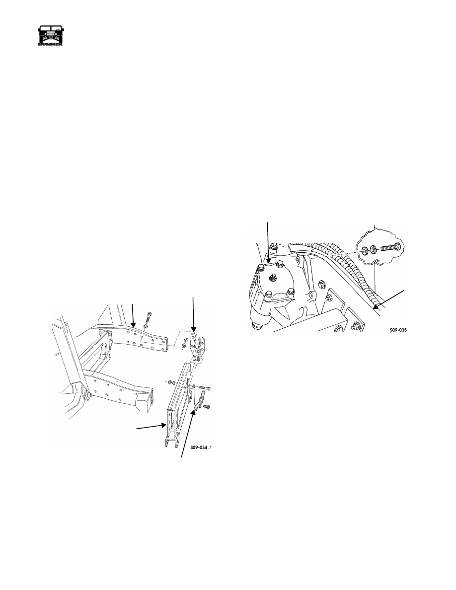
Remove three bolts, lockwashers, and washers and pull
steering gear away from left frame rail (Figure 9-146).
9.
Remove three bolts and clamps from two vent line
brackets and crossmember (Figure 9-147).
Figure 9-146: Steering Gear and Left Frame Rail
Location
WARNING: To avoid personal injury, support cross-
member during removal.
NOTE:
Note direction of bolts for installation.
10. Remove four locknuts, washers, bolts, washers, and vent
line bracket securing rear crossmember to right frame rail.
11. Remove three locknuts, washers, bolts, washers, and vent
line bracket securing rear crossmember to left frame rail.
12. Remove bolt and washer securing rear crossmember to left
frame rail.
13. Remove six locknuts, washers, bolts, and washers sec-
uring rear crossmember to left and right rear crossmember
mounting brackets.
14. Slide rear crossmember and mounting brackets down and
out from under vehicle.
15. Remove mounting brackets from rear crossmember.
FRAME RAIL
CROSSMEMBER
HARNESS
FRONT
MOUNTING BRACKET
CROSSMEMBER
STEERING GEAR
LEFT
FRAME
RAIL
9-62
Axles, Suspension, and Frame
_________________________________________
®
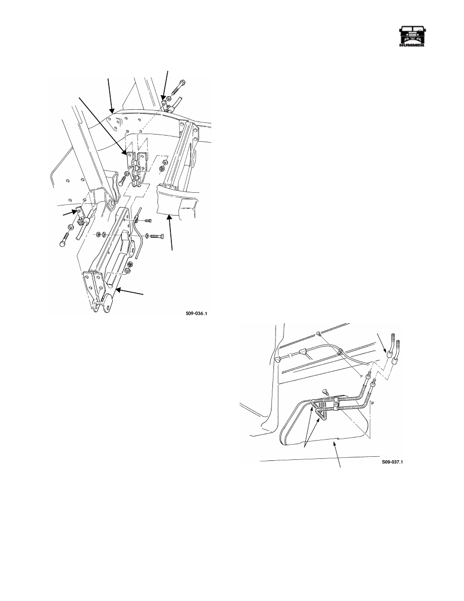
Figure 9-147: Rear Crossmember Replacement
Installation
1.
Install left and right rear crossmember mounting brackets
on rear crossmember (Figure 9-147).
2.
Install rear crossmember and mounting brackets on frame
rails.
3.
Apply thread-locking compound to hole and secure
crossmember mounting bracket to left frame rail with
washer and bolt. Tighten bolt to 65-78 lb-ft (88-106 N•m).
4.
Secure crossmember mounting bracket to left frame rail
with vent line bracket, three washers, bolts, washers, and
locknuts. Do not tighten bolts.
5.
Secure crossmember mounting bracket to right frame rail
with vent line bracket, four washers, bolts, washers, and
locknuts. Do not tighten bolts.
6.
Install six washers, bolts, washers, and locknuts securing
rear crossmember to left and right mounting brackets.
Tighten bolts to 90 lb-ft (122 N•m).
7.
Tighten three bolts on mounting bracket and left frame rail
to 90 lb-ft (122 N•m).
8.
Tighten four bolts on mounting bracket and right frame
rail to 90 lb-ft (122 N•m).
9.
Secure vent line to rear crossmember and two vent line
brackets with three clamps and bolts.
10. Secure steering gear to left frame rail with three washers,
lockwashers, and bolts. Tighten bolts to 60 lb-ft (81 N•m)
(Figure 9-146).
11. Install axle support brackets and side mounting brackets.
12. Install axle.
13. Install lower control arms.
14. Install right front caliper-to-tee brake line.
15. Install right front upper control arm.
16. Install lower radiator tube.
17. Install radiator.
REAR SUSPENSION FRONT CROSSMEMBER
REPLACEMENT
Removal
1.
Remove rear-front tiedown brackets.
2.
Remove axle (Section 6).
3.
Remove axle support brackets and side mounting brackets.
4.
Remove rear lower control arms.
5.
Remove three bolts and clamps securing brake line and
two vent lines to front crossmember (Figure 9-148) and
(Figure 9-149).
6.
Remove brake line from tee and tube coupling.
Figure 9-148: Brake Line and Tube Coupling
Location
7.
Remove two locknuts, washers, bolts, washers, and two
radius rods from crossmember mounting brackets
(Figure 9-150).
VENT LINE BRACKET
LEFT
CROSSMEMBER
VENT LINE
REAR CROSSMEMBER
RIGHT FRAME RAIL
BRACKET
MOUNTING
BRACKET
FRAME RAIL
TUBE COUPLING
BRAKE LINE
FRONT CROSSMEMBER
________________________________________
Axles, Suspension, and Frame 9-63
®
05745159
WARNING: To avoid personal injury, support cross-
member during removal.
8.
Loosen six locknuts securing front crossmember to
crossmember mounting brackets.
9.
Slide front crossmember down and out from under
vehicle.
10. Remove six locknuts, washers, bolts, washers, and two
crossmember mounting brackets from front crossmember.
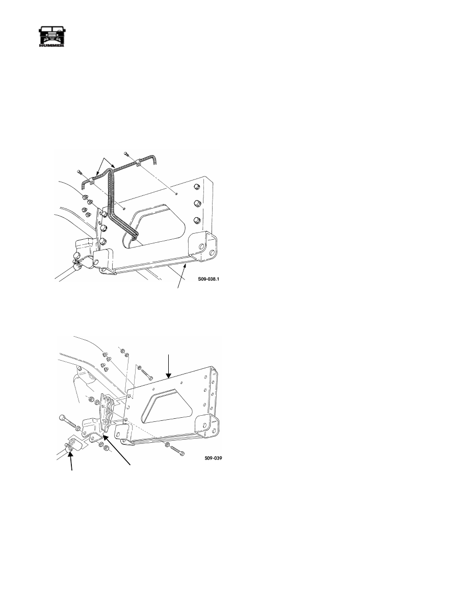
Figure 9-149: Brake Line and Vent Lines Location
Figure 9-150: Front Crossmember Assembly
Replacement
Installation
1.
Install two crossmember mounting brackets on front cross-
member with six washers, bolts, washers, and locknuts.
Tighten locknuts to 90 lb-ft (122 N•m) (Figure 9-150).
2.
Install front crossmember on frame rails.
3.
Install rear-front tiedown brackets.
4.
Install radius rods in crossmember mounting brackets with
two washers, bolts, washers, and locknuts. Tighten
locknuts to 260 lb-ft (353 N•m).
5.
Install brake line on tee and tube coupling (Figure 9-148)
and (Figure 9-150).
6.
Secure brake line and two vent lines to front crossmember
with three clamps and bolts.
7.
Install axle support brackets and side mounting brackets.
8.
Install axle.
9.
Install rear lower control arms.
10. Bleed rear brakes.
BRAKE
FRONT
LINE
CROSSMEMBER
FRONT
CROSSMEMBER
RADIUS ROD
CROSSMEMBER
MOUNTING BRACKET
9-64
Axles, Suspension, and Frame
_________________________________________
®
FRAME INSPECTION
General Information
The frame rails are constructed by arc-welding two “C” chan-
nels of preformed steel together to form a box cross section.
The frame rails are internally reinforced at bolt hole locations
by bushings or full cross-section spacers to prevent channels
from collapsing from attaching load. The frame is made by
bolting two non-identical frame rails to crossmembers. Cross-
members are held to stringent dimensional tolerances and
therefore must be replaced if damaged.
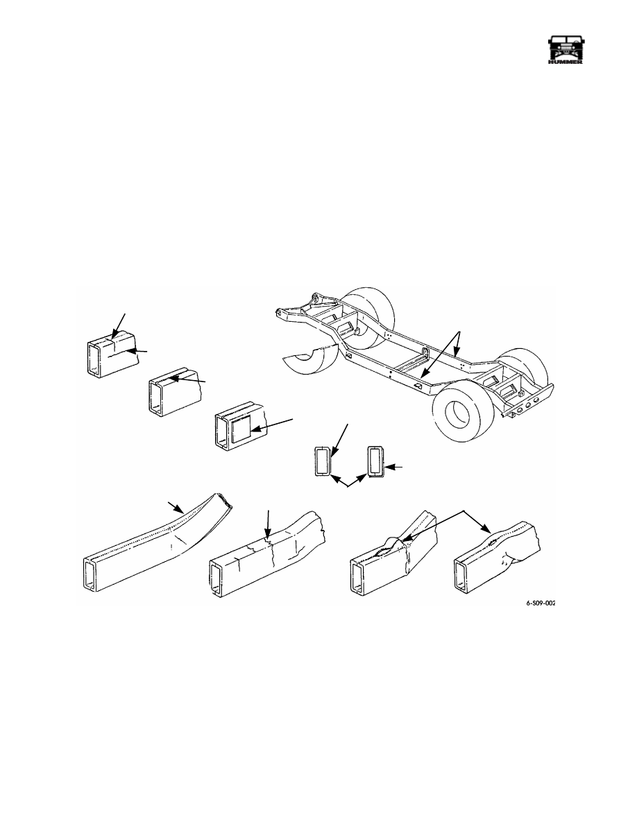
INSPECTION
The visual inspection is the first and most critical step in form-
ing a decision of whether to repair or replace a damaged frame
component (Figure 9-151). Factors to consider when making a
visual inspection are:
1.
Twisted frame rails are not repairable and must be
replaced.
2.
Transverse tears or breaks extending across or into both
upper or lower corners are not repairable by welding.
3.
Short longitudinal cracks up to 6 inches (15.2 cm) or split
welds can be repaired by heli-arc welding.
Figure 9-151: Frame Damage
TRANSVERSE
CRACK
LONGITUDINAL CRACK
MANUFACTURING WELD
TWISTED RAIL
FRAME RAILS
CRACK
COMPLETE
TRANSVERSE
BUCKLE
LAP WELD
REINFORCEMENT
REINFORCEMENT
(NO LESS THAN 6-IN.
(15.2 CM) IN LENGTH)
Нет комментариевНе стесняйтесь поделиться с нами вашим ценным мнением.
Текст