Hummer H1 (2002+). Manual — part 138
________________________________________
Axles, Suspension, and Frame 9-13
®
05745159
Figure 9-24: Dial Indicator Positioning
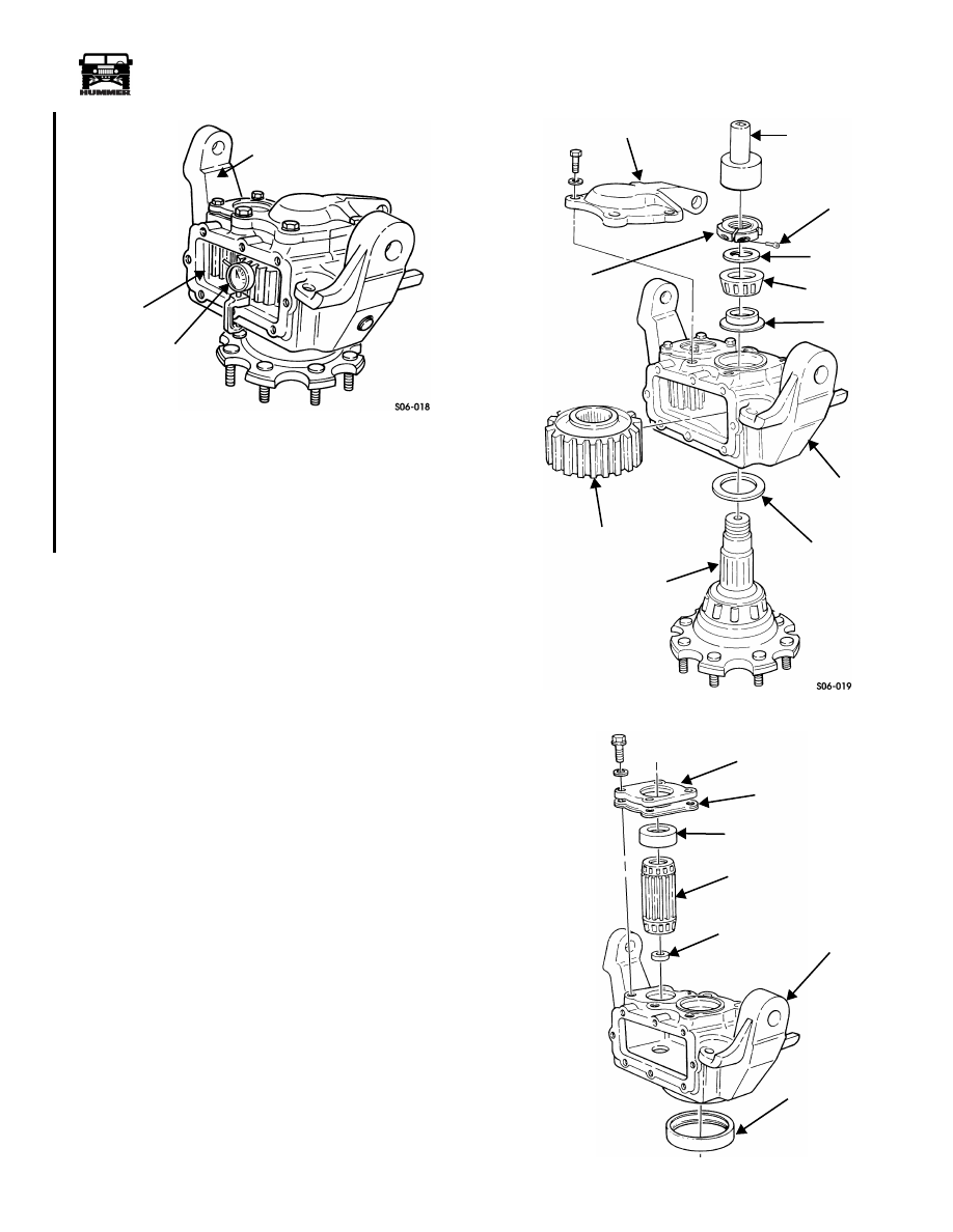
5.
Remove four bolts, washers, and steering arm cover from
geared hub (Figure 9-25).
6.
Remove clamp nut lock screw from clamp nut.
7.
Using clampnut socket SBAS-07M, remove clamp nut and
keyed washer from spindle.
NOTE:
It may be necessary to lightly tap threaded end of spin-
dle to release it from the inner spindle bearing.
8.
Lift geared hub off spindle.
9.
Remove inner bearing, bearing spacer, and driven gear
from geared hub.
10. Remove outer bearing spacer from spindle.
11. Remove four bolts, washers, drive gear retainer, shim
gasket, inboard bearing cup, and drive gear from geared
hub (Figure 9-26).
12. Remove retaining washer from inside drive gear or geared
hub.
13. Remove spindle seal from geared hub. Discard seal.
14. Remove input seal from drive gear retainer. Discard seal
(Figure 9-27).
Figure 9-25: Geared Hub Breakdown
Figure 9-26: Drive Gear Removal
DRIVE
DIAL
GEARED HUB
INDICATOR
GEAR
J–8001
STEERING ARM COVER
CLAMPNUT
CLAMPNUT
CLAMPNUT
LOCK SCREW
KEYED
INNER
BEARING
GEARED HUB
OUTER
BEARING
SPACER
SPINDLE
DRIVEN GEAR
SPACER
BEARING
WASHER
SOCKET
DRIVE GEAR RETAINER
SHIM GASKET
INBOARD
BEARING CUP
DRIVE GEAR
RETAINING
GEARED HUB
SPINDLE SEAL
WASHER
S06-020
4-1-00
9-14
Axles, Suspension, and Frame
_________________________________________
®
Figure 9-27: Input Seal Removal
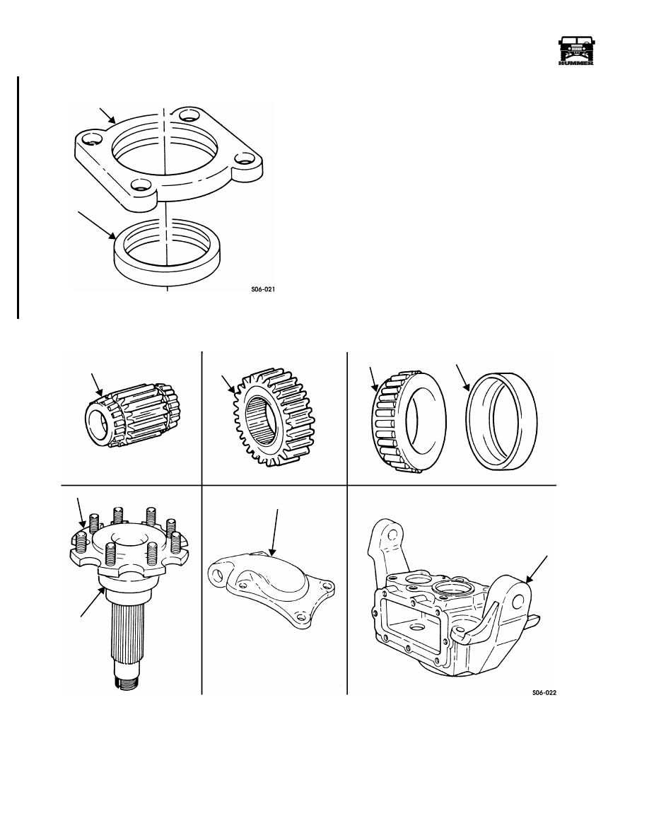
Inspection
NOTE:
Clean all components, examine for wear or damage,
and replace if necessary. Drive and driven gears must be re-
placed as matched set (Figure 9-28).
1.
Inspect splines and gear teeth on drive gear and driven
gear for damage.
2.
Inspect spindle for damage and rough or corroded sealing
surface.
3.
Inspect all bearings and bearing races for damage.
4.
Inspect steering arm cover for damage.
5.
Inspect geared hub and all threaded holes for damage.
Repair any damaged holes using thread repair inserts.
Figure 9-28: Geared Hub Component Appearance
DRIVE GEAR RETAINER
INPUT SEAL
DRIVE GEAR
DRIVEN
BEARING
SPINDLE
SEALING
STEERING ARM COVER
GEARED HUB
SURFACE
BEARING RACE
GEAR
4-1-00

________________________________________
Axles, Suspension, and Frame 9-15
®
05745159
Assembly
1.
Place the new output seal on the installer J–44906, with
the seamed side of the stainless steel perimeter facing
toward the geared hub and drive the seal in until the
installer bottoms out on the geared hub surface. The seal
will be recessed in the geared hub approximately 0.185".
This dimension is critical and must be achieved using the
special tool. (Figure 9-29).
Figure 9-29: Spindle Seal Installation
2.
Using driver handle J–8092 and input seal installer
J-44905, install input seal in drive gear retainer. Place the
new primary seal on the installer with the seamed side of
the stainless steel perimeter facing toward the drive gear
retainer. Drive the seal in until the installer bottoms against
the drive gear retainer. The seal will be recessed in the
drive gear retainer approximately 0.310". This dimension
is critical and must be achieved using the special tool.
(Figure 9-30).
Figure 9-30: Input Seal Installation
3.
Install retaining washer in shallow end of drive gear
(Figure 9-31).
Figure 9-31: Retaining Washer Location
4.
Install drive gear and inboard bearing cup in geared hub.
5.
Apply thread-locking compound on bolts. Secure shim
gasket and drive gear retainer to geared hub with four
washers and bolts. Tighten bolts to 25-35 lb-ft (40-48
N•m).
6.
Mount dial indicator on geared hub and index indicator to
register on end of drive gear (Figure 9-32).
Figure 9-32: Dial Indicator Positioning
7.
Move drive gear up and down to read end play. End play
should be 0.001-0.006 in. (0.03-0.15 mm). If end play is
00-S09-004
DRIVER
SPINDLE
SPINDLE SEAL
GEARED HUB
SEAL INSTALLER
HANDLE
J–44906
J–8092
00-S09-003
DRIVER HANDLE
INPUT SEAL
DRIVE GEAR
RETAINER
INSTALLER
J–8092
J–44905
DRIVE GEAR RETAINER
SHIM GASKET
INBOARD
DRIVE GEAR
RETAINING
GEARED HUB
BEARING CUP
WASHER
DIAL INDICATOR
GEARED HUB
DRIVE GEAR
4-1-00
9-16
Axles, Suspension, and Frame
_________________________________________
®
incorrect, add or subtract shim gaskets and recheck end
play.
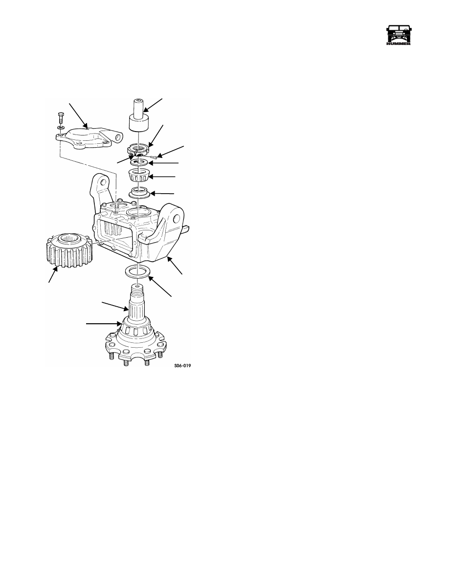
8.
Install driven gear and bearing spacer in geared hub
(Figure 9-33).
Figure 9-33: Geared Hub Driven Gear Installation
9.
Install outer bearing spacer on spindle.
10. Lower geared hub onto spindle and align splines on driven
gear with splines on spindle. Ensure outer spindle bearing
seats in bearing cup.
11. Install inner bearing and keyed washer on spindle.
NOTE:
After clampnut lock screw is installed into clampnut,
clampnut must be completely installed on spindle within a ten
minute limit.
12. Tighten clampnut lock screw three to five turns into clamp
nut.
CAUTION:
Ensure clampnut is installed on spindle with boss
(protruding side) facing inward toward bearing and large
chamfer side with engraved part number facing away from
bearing.
13. Apply a thin coat of grease to boss (protruding side) of
clampnut and install clampnut on spindle.
NOTE:
If an excessive amount of torque (18-26 lb-in. (2-3
N•m)) is required to tighten clampnut lock screw to remove
clampnut wobble, remove screw. Ensure threads of clampnut
are clean and free of Loctite. Replace screw with a new one, or
remove all previously applied Loctite from threads of old
screw and apply fresh Loctite 272 to old screw threads prior to
reinstallation. Use a hexagonhead socket with a calibrated
torque wrench to tighten and check torque of screw.
14. Tighten clampnut lock screw until all clampnut wobble is
removed and clamp nut can still be rotated by hand.
15. Using clampnut socket J–42545, tighten clamp nut to 40
lb-ft (54 N•m). Rotate spindle five revolutions both
clockwise and counterclockwise to seat bearings.
16. Loosen and retighten clampnut to 25 lb-ft (34 N•m).
NOTE:
Ensure clampnut does not move while clampnut lock
screw is being tightened.
17. Using a hexagon-head socket and pre-set calibrated torque
wrench, tighten clampnut lock screw to 90 lb-in. (10
N•m).
18. Mark a temporary line across end of spindle and clampnut.
NOTE:
Using a feeler gauge, ensure a gap exists between
clampnut gap surfaces. If no gap exists, remove and discard
clampnut lock screw and clampnut. Acquire new screw and nut
and repeat steps 12-18.
19. Using preset torque wrench, apply pressure to clamp nut in
a counterclockwise direction until torque wrench clicks,
indicating 90 lb-ft (122 N•m) of loosening torque was
applied to clampnut.
NOTE:
Clampnut should not move. To verify no movement
occurred, check temporary mark across spindle and clampnut.
If clampnut moves, remove and discard clampnut lock screw
and clampnut. Repeat steps 12-19 with new screw and nut.
20. Paint or scribe a permanent line across end of spindle and
clampnut.
NOTE:
Immediately install steering arm cover after applica-
tion of sealer.
21. Clean sealing surfaces on geared hub and steering arm
cover. Apply anaerobic sealer to steering arm cover and
secure steering arm cover to geared hub.
NOTE:
Make sure bolts and holes are free of old Loctite.
22. Apply thread-locking compound to bolts. Secure steering
arm cover to geared hub with four washers and bolts.
Tighten bolts to 65 lb-ft (88 N•m).
STEERING ARM COVER
CLAMPNUT
CLAMPNUT
LOCK SCREW
KEYED
INNER
BEARING
GEARED HUB
OUTER
BEARING
SPACER
SPINDLE
DRIVEN GEAR
SPACER
BEARING
WASHER
CLAMPNUT SOCKET
OUTER SPINDLE
BEARING
GAP
4-1-00
Нет комментариевНе стесняйтесь поделиться с нами вашим ценным мнением.
Текст