Hummer H1 (2002+). Manual — part 139
________________________________________
Axles, Suspension, and Frame 9-17
®
05745159
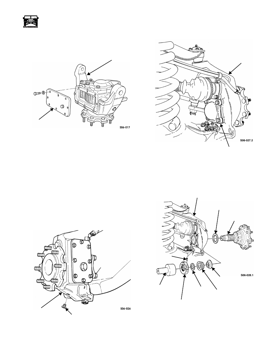
23. Clean sealing surfaces on geared hub and side cover.
Apply anaerobic sealer to side cover and install on geared
hub (Figure 9-34).
Figure 9-34: Geared Hub Side Cover Removal
NOTE:
Make sure bolts and holes are free of old Loctite.
24. Apply thread-locking compound to bolts. Secure side
cover to geared hub with eight washers and bolts. Tighten
bolts to 8-13 lb-ft (11-18 N•m).
25. Install geared hub.
GEARED HUB SPINDLE SEAL REPLACEMENT
Removal
1.
Remove wheel.
2.
Remove drainplug from geared hub and drain geared hub
oil. Install drainplug in geared hub. Tighten drainplug to
8-13 lb-ft (11-18 N•m) (Figure 9-35).
Figure 9-35: Geared Hub Drainplug Removal
3.
Remove four bolts, washers, and steering arm cover from
geared hub (Figure 9-36).
Figure 9-36: Geared Hub Steering Arm
Cover Removal
4.
Remove clampnut lock screw from clampnut
(Figure 9-37).
Figure 9-37: Clamp Nut Removal
5.
Using clampnut socket J–42545, remove clampnut and
keyed washer from spindle.
GEARED HUB
SIDE COVER
GEARED HUB
DRAINPLUG
STEERING ARM COVER
GEARED HUB
GEARED HUB
OUTER BEARING
SPINDLE
BEARING
INNER
KEYED
CLAMPNUT
CLAMPNUT
CLAMPNUT
LOCK SCREW
SOCKET
WASHER
BEARING
SPACER
SPACER
J-42545
9-18
Axles, Suspension, and Frame
_________________________________________
®
6.
Remove spindle, bearing spacer, inner bearing, and outer
bearing spacer from geared hub.
7.
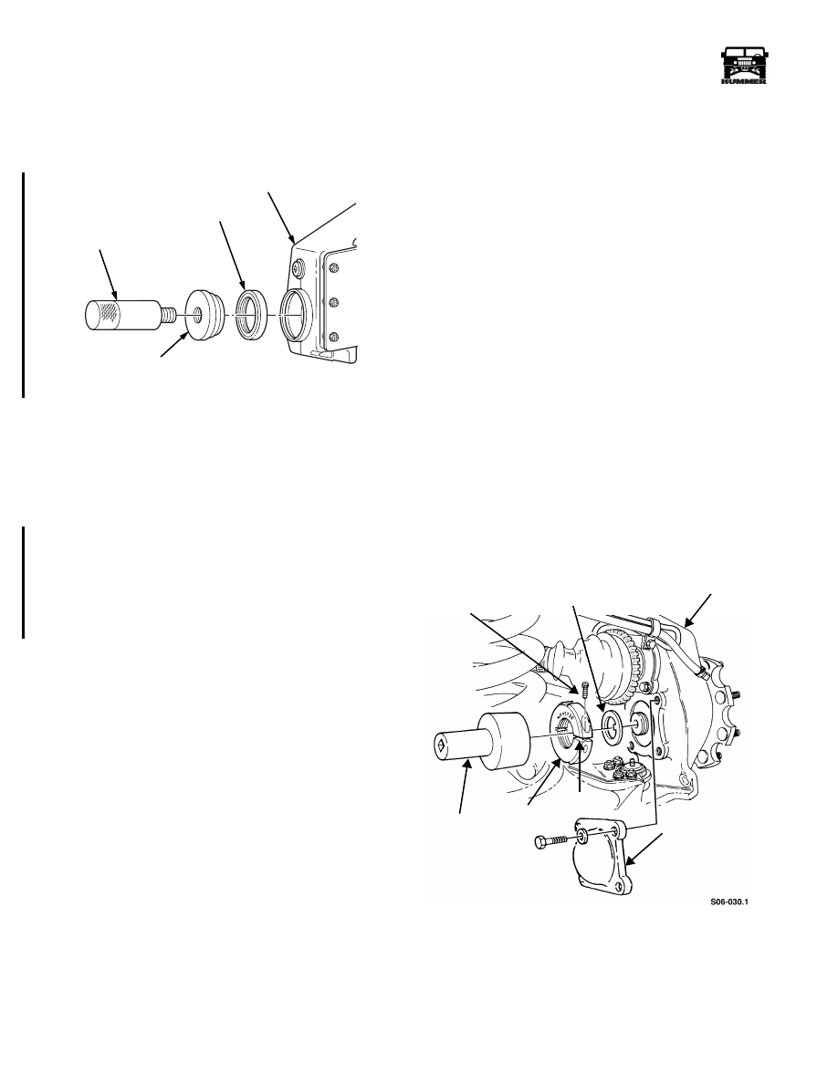
Remove spindle seal from geared hub. Discard spindle
seal (Figure 9-38).
Figure 9-38: Spindle Seal Removal
Cleaning and Inspection
1.
Inspect spindle for rough or corroded sealing surface.
Replace if damaged (Figure 9-37).
2.
Inspect bearings for damage. Replace if damaged.
Installation
1.
Place the new output seal on the installer, with the seamed
side of the stainless steel perimeter facing toward the
geared hub and drive the seal in until the installer bottoms
out on the geared hub surface. The seal will be recessed in
the geared hub approximately 0.185". This dimension is
critical and must be achieved using the special tool.
(Figure 9-38).
2.
Coat seal with lubricating oil.
3.
Install outer bearing spacer and spindle in geared hub
(Figure 9-37).
4.
Install bearing spacer, inner bearing, and keyed washer on
spindle.
NOTE:
After clampnut lock screw is installed into clampnut,
clampnut must be completely installed on spindle within a ten
minute limit.
5.
Tighten clampnut lock screw three to five turns into
clampnut.
CAUTION:
Ensure clampnut is installed on spindle with boss
(protruding side) facing inward toward bearing and large
chamfer side with engraved part number facing away from
bearing.
6.
Apply a thin coat of grease to boss (protruding side) of
clampnut and install clampnut on spindle.
7.
If an excessive amount of torque (18-26 lb-in. (2-3 N•m))
is required to tighten clampnut lock screw to remove
clampnut wobble, remove clampnut lock screw. Ensure
threads of clampnut are clean and free of Loctite. Replace
screw with a new one or remove all previously applied
Loctite from threads of old screw and apply fresh Loctite
272 to old screw threads prior to reinstallation. Use hex
socket and torque wrench to tighten and check screw
torque.
8.
Tighten clampnut lock screw until all clampnut wobble is
removed but clampnut can still be rotated by hand.
9.
Using clampnut socket J–42545, tighten clampnut to 40
lb-ft (54 N•m) (Figure
9-39). Rotate spindle five
revolutions both clockwise and counterclockwise to seat
bearings.
10. Loosen and retighten clampnut to 25 lb-ft (34 N•m).
NOTE:
Ensure clampnut does not move while clampnut lock
screw is being tightened.
11. Tighten clamp nut lock screw to 90 lb-in. (10 N•m).
12. Mark a temporary line across end of spindle and clamp
nut. Then, using a feeler gauge, ensure a gap exists
between clampnut gap surfaces. If no gap exists, remove
and discard clampnut lock screw and clampnut. Acquire
new screw and nut and repeat steps 5-12.
13. Apply 90 lb-ft (122 N•m) of loosening torque to clampnut.
Clampnut should not move. To verify no movement
occurred, check temporary mark across spindle and
clampnut. If clampnut moved, remove and discard
clampnut lock screw and clampnut. Repeat steps 5-13 with
new screw and nut.
Figure 9-39: Clampnut Installation
14. Paint or scribe a permanent line across end of spindle and
clampnut.
15. Clean sealing surfaces on geared hub and steering arm
cover. Apply Loctite 518 sealant to steering arm cover and
install on geared hub.
00-S09-004
DRIVER HANDLE
SPINDLE SEAL
GEARED HUB
INSTALLER
J–8092
J–44906
CLAMPNUT
CLAMPNUT
KEYED WASHER
GEARED HUB
STEERING ARM
CLAMP
COVER
LOCK SCREW
SOCKET
SBAS-07M
GAP
NUT
4-1-00
________________________________________
Axles, Suspension, and Frame 9-19
®
05745159
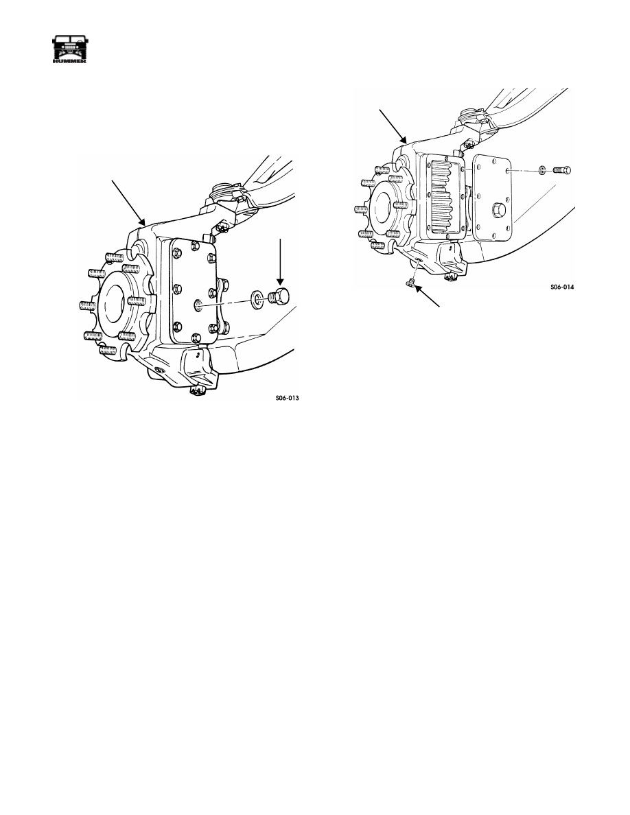
16. Apply thread-locking compound to bolt threads and install
steering arm cover on geared hub with four washers and
bolts. Tighten bolts to 65 lb-ft (88 N•m).
17. Remove fill plug and washer from geared hub
(Figure 9-40).
Figure 9-40: Geared Hub Fill Plug Location
18. Fill geared hub to proper oil level (Section 1).
19. Secure washer and fill plug to geared hub. Tighten fill
plug to 8-13 lb-ft (11-18 N•m).
20. Install wheel.
GEARED HUB SPINDLE BEARING ADJUSTMENT
Adjustment
1.
Remove wheel.
2.
Remove drainplug and drain geared hub oil. Install
drainplug into geared hub. Tighten drainplug to 8-13 lb-ft
(11-18 N•m) (Figure 9-41).
3.
Remove four bolts, washers, and steering arm cover from
geared hub. Push steering arm cover away from geared
hub (Figure 9-43).
4.
Remove clampnut lock screw from clampnut.
5.
Using clampnut socket, remove clampnut and keyed
washer from spindle.
6.
After clampnut lock screw is installed into clampnut,
clampnut must be completely installed on spindle within a
ten minute limit.
Figure 9-41: Geared Hub Drainplug Location
7.
Tighten clampnut lock screw three to five turns into
clampnut.
CAUTION: Ensure clampnut is installed on spindle with boss
(protruding side) facing inward toward bearing and large
chamfer side with engraved part number facing away from
bearing.
8.
Apply a thin coat of grease to boss (protruding side) of
clamp nut and install clamp nut on spindle.
NOTE:
If an excessive amount of torque (18-26 lb-in. (2-3
N•m)) is required to tighten clampnut lock screw to remove
clampnut wobble, remove screw. Ensure threads of clampnut
are clean and free of Loctite. Replace screw with a new one or
remove all previously applied Loctite from threads of old
screw and apply fresh Loctite 272 to old screw threads prior to
reinstallation. Use a hex socket and torque wrench to tighten
and check screw torque.
9.
Tighten clampnut lock screw until all clampnut wobble is
removed and clampnut can still be rotated by hand.
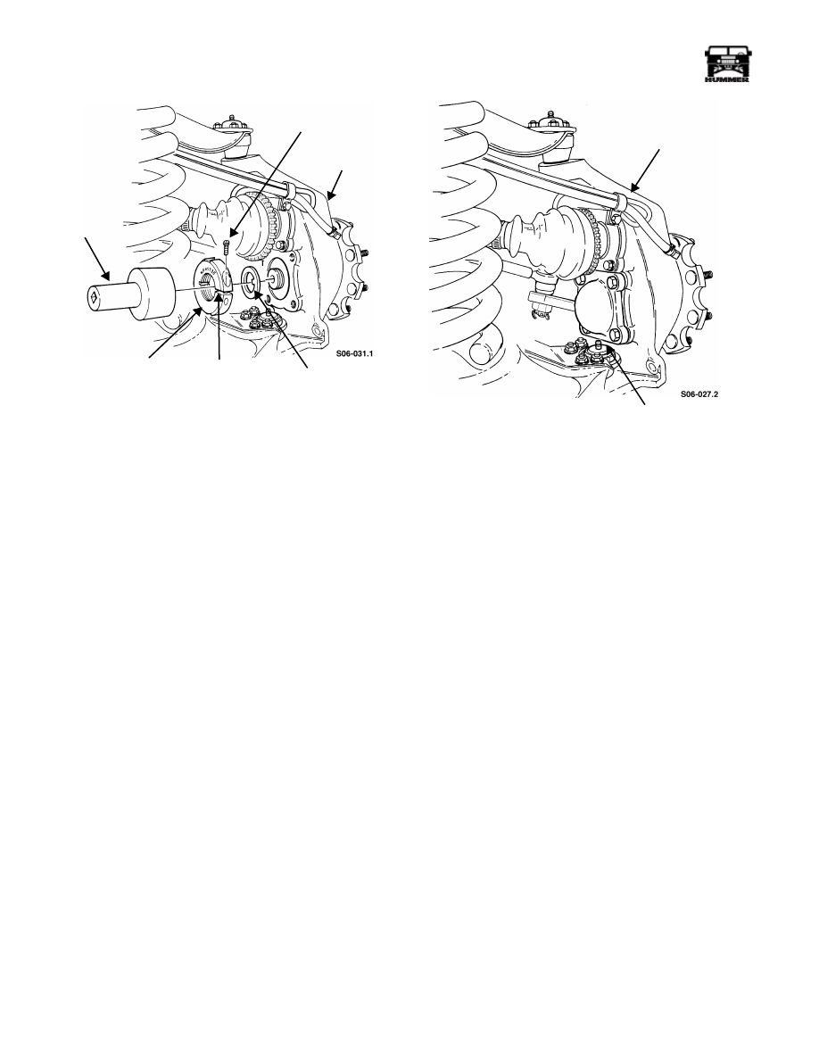
10. Using clampnut socket SBAS-07M, tighten clampnut to
40 lb-ft (54 N•m). Rotate spindle five revolutions both
clockwise and counterclockwise to seat bearings
(Figure 9-42).
GEARED HUB
FILL PLUG
GEARED HUB
DRAINPLUG
9-20
Axles, Suspension, and Frame
_________________________________________
®
Figure 9-42: Clampnut Installation
11. Loosen and retighten clampnut to 25 lb-ft (34 N•m).
NOTE:
Ensure clampnut does not move while clampnut lock
screw is being tightened.
12. Using a hexagon-head socket and pre-set calibrated torque
wrench, tighten clampnut lock screw to 90 lb-in. (10
N•m).
13. Mark a temporary line across end of spindle and clampnut.
NOTE:
Using a feeler gauge, ensure a gap exists between
clampnut gap surfaces. If no gap exists, remove and discard
clampnut lock screw and clampnut. Acquire new screw and nut
and repeat steps 6-12.
14. Using pre-set torque wrench, apply pressure to clampnut
in counterclockwise direction until torque wrench clicks,
indicating 90 lb-ft (122 N•m) of loosening torque was
applied to clampnut.
NOTE:
Clampnut should not move. To verify no movement
occurred, check temporary mark across spindle and clampnut.
If clampnut moved, remove and discard clampnut lock screw
and clampnut. Repeat steps 6-13 with new screw and nut.
15. Paint or scribe a permanent line across end of spindle and
clampnut.
NOTE:
Immediately install steering arm cover after applica-
tion of sealant.
16. Clean sealing surfaces on geared hub and steering arm
cover. Apply anaerobic sealant to steering arm cover and
install on geared hub (Figure 9-43).
Figure 9-43: Steering Arm Cover Installation
NOTE:
Thoroughly clean old Loctite before applying fresh
Loctite.
17. Apply thread-locking compound to bolt threads and secure
steering arm cover to geared hub with four washers and
bolts. Tighten bolts to 65 lb-ft (88 N•m).
18. Remove fill plug and washer from geared hub
(Figure 9-40).
19. Fill geared hub to proper oil level (Section 1).
20. Secure washer and fill plug to geared hub. Tighten fill
plug to 8-13 lb-ft (11-18 N•m).
CLAMPNUT
CLAMPNUT
GEARED
KEYED
CLAMPNUT
LOCK SCREW
SOCKET
WASHER
HUB
SBAS-07M
GAP
GEARED HUB
STEERING ARM
COVER
Нет комментариевНе стесняйтесь поделиться с нами вашим ценным мнением.
Текст