Hummer H1 (2002+). Manual — part 137
__________________________________________
Axles, Suspension, and Frame 9-9
®
05745159
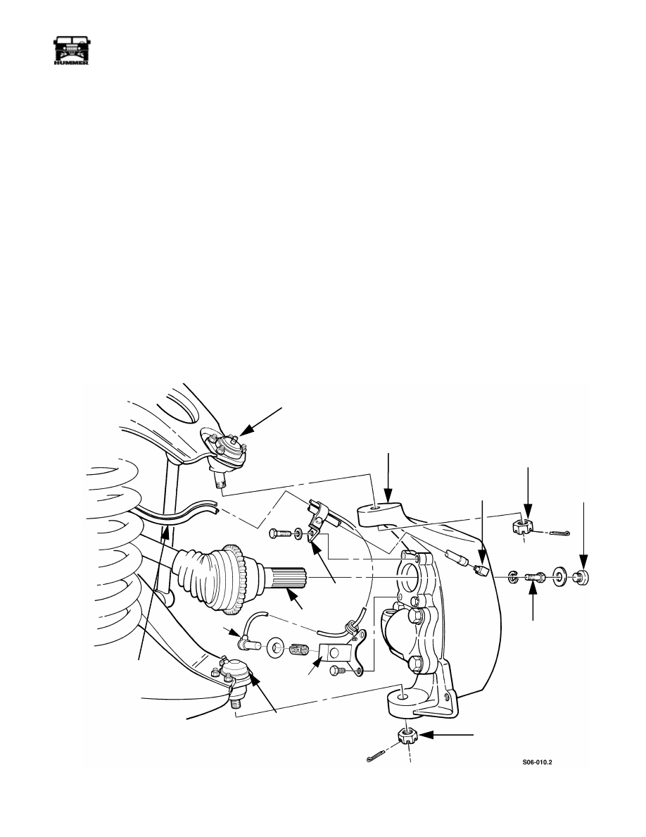
Installation
WARNING: To avoid injury and damage to equip-
ment, support geared hub during removal and installa-
tion.
1.
Position geared hub between upper and lower control arms
and secure upper ball joint to geared hub with slotted nut,
but do not tighten (Figure 9-15).
2.
Secure lower ball joint to geared hub with slotted nut, but
do not tighten.
NOTE:
If necessary, tighten slotted nut to install cotter pin.
When slotted nuts are tightened to prescribed torque values,
cotter pins must have a minimum of 50% engagement with the
nut slots.
3.
Tighten slotted nut securing upper ball joint to geared hub
to 65 lb-ft (88 N•m). Install cotter pin.
4.
Slide halfshaft into geared hub.
NOTE:
Make sure mounting hole and bolt are cleared of old
Loctite.
5.
Apply thread-locking compound to halfshaft retaining bolt
and secure halfshaft to geared hub with lockwasher and
halfshaft retaining bolt. Tighten halfshaft retaining bolt to
37 lb-ft (50 N•m).
6.
Secure washer and access plug to geared hub. Tighten
access plug to 8-13 lb-ft (11-18 N•m).
NOTE:
If necessary, tighten slotted nut to install cotter pin.
7.
Tighten slotted nut securing lower ball joint to geared hub
to 73 lb-ft (99 N•m). Install cotter pin.
8.
Insert tie rod end into geared hub and secure with washer
and slotted nut. Tighten slotted nut to 70 lb-ft (95 N•m).
Install cotter pin (Figure 9-14).
9.
Connect vent line to geared hub fitting (Figure 9-17).
10. Install speed sensor in sensor bracket and push in until
sensor contacts tone wheel on halfshaft.
Figure 9-15: Geared Hub Replacement
UPPER BALL JOINT
GEARED HUB
SLOTTED NUT
GEARED HUB
ACCESS
HALFSHAFT
RETAINING
BOLT
SLOTTED NUT
VENT LINE
VENT LINE
FITTING
PLUG
LOWER
BALL JOINT
BRACKET
HALFSHAFT
SPEED
SENSOR
SENSOR
BRACKET
9-10
Axles, Suspension, and Frame
_________________________________________
®
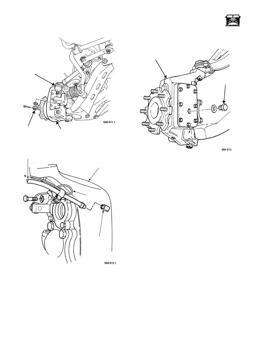
Figure 9-16: Tie Rod End Into Geared Hub
Figure 9-17: Vent Line
11. Secure vent line, speed sensor lead and clamp to geared
hub with washer and bolt. Tighten bolt to 38 lb-ft (52
N•m) (the left side of vehicle uses two p-clamps to secure
the speed sensor lead to the geared hub).
12. Install speed sensor and retaining sleeve into speed sensor
bracket and push in until the sensor touches the tone
wheel.
13. Remove fill plug and washer from geared hub
(Figure 9-18).
Figure 9-18: Geared Hub Fill Plug
14. Fill geared hub to proper oil level (Section 1).
15. Install washer and fill plug on geared hub. Tighten fill
plug to 8-13 lb-ft (11-18 N•m).
16. Install wheel.
17. Check alignment.
TIE ROD END
SLOTTED NUT
GEARED HUB
VENT LINE
GEARED HUB
GEARED HUB
FITTING
SPEED
SENSOR
LEAD
GEARED HUB
FILL PLUG

________________________________________
Axles, Suspension, and Frame 9-11
®
05745159
GEARED HUB SIDE COVER REPLACEMENT
NOTE:
Geared hub side cover replacement procedures are
basically the same for front and rear covers. This procedure
covers the front side cover.
Removal
1.
Remove wheel.
2.
Remove drainplug from geared hub and drain geared hub
(Figure 9-19).
3.
Install drainplug in geared hub.
4.
Remove eight bolts, washers, and side cover from geared
hub.
Figure 9-19: Geared Hub Side Cover Replacement
Cleaning and Inspection
NOTE:
Clean all components, examine for wear or damage,
and replace if necessary.
1.
Using solvent, clean and dry side cover.
2.
Inspect side cover for damage.
Installation
1.
Apply anaerobic sealant to side cover and allow to set until
tacky.
2.
Apply thread-locking compound to bolts and install side
cover to geared hub with eight washers and bolts. Tighten
bolts to 15 lb-ft (20 N•m).
3.
Fill geared hub to proper oil level (Section 1).
4.
Install wheel.
GEARED HUB INPUT SEAL REPLACEMENT
Removal
1.
Remove wheel.
2.
Remove access plug and washer from geared hub
(Figure 9-15).
3.
Remove halfshaft retaining bolt, lockwasher, and halfshaft
from geared hub. Remove v-seal from c-v joint Figure 9.
CAUTION:
Shim gaskets must be reused to maintain proper
drive gear bearing adjustment.
4.
Remove bolt, washer, and vent line/speed sensor lead
bracket from drive gear retainer (Figure 9-20).
Figure 9-20: Geared Hub Shim Gasket Location
5.
Remove remaining bolts, washers, speed sensor bracket,
drive gear retainer, and shim gasket(s) from geared hub.
6.
Secure drive gear retainer in vise with inserts and remove
input seal. Discard input seal (Figure 9-21).
GEARED HUB
SIDE COVER
DRAINPLUG
VENT LINE BRACKET
DRIVE GEAR
RETAINER
SHIM GASKET
GEARED
HUB
4-1-00

9-12
Axles, Suspension, and Frame
_________________________________________
®
Figure 9-21: Input Seal Installation
Installation
1.
Using driver handle J–8092 and input seal installer
J-44905, install input seal in drive gear retainer. Place the
new primary seal on the installer with the seamed side of
the stainless steel perimeter facing toward the drive gear
retainer. Drive the seal in until the installer bottoms against
the drive gear retainer. The seal will be recessed in the
drive gear retainer approximately 0.310". This dimension
is critical and must be achieved using the special tool.
(Figure 9-21).
2.
Secure shim gasket(s) and drive gear retainer to geared
hub with washers and bolts (Figure 9-20).
3.
Secure vent line bracket and speed sensor bracket to drive
gear retainer with washers and bolts. Tighten all four bolts
to 38 lb-ft (52 N•m).
4.
Coat lip of input seal with gear oil (Figure 9-21).
5.
Stretch the v-seal over the seal area of the halfshaft with
the thick side against the c-v joint. Lubricate the thin side
of the v-seal with an all purpose grease. This portion of the
v-seal will contact the stainless steel portion of the
primary seal when the halfshaft is installed.
Figure 9-21.1 V-Seal Replacement
NOTE:
Be sure that bolt and bolt hole are cleaned of old Loctite.
6.
Apply thread-locking compound to halfshaft retaining bolt
and secure halfshaft to geared hub with lockwasher and
halfshaft retaining bolt. Tighten halfshaft retaining bolt to
37 lb-ft (50 N•m) (Figure 9-22).
7.
Secure washer and access plug onto geared hub. Tighten
access plug to 8-13 lb-ft. (11-18 N•m).
8.
Install wheel.
Figure 9-22: Halfshaft and Geared Hub
GEARED HUB REPAIR
Disassembly
1.
Remove geared hub.
2.
Position geared hub with spindle supporting geared hub
(Figure 9-23).
Figure 9-23: Geared Hub Disassembly
3.
Remove eight bolts, washers, and side cover from geared
hub.
CAUTION:
If backlash between drive and driven gears is
more than 0.018 in. (0.46 mm), both gears must be replaced.
4.
Mount dial indicator J–8001 on geared hub and index
indicator to register from one drive gear tooth. Move drive
gear back and forth while holding driven gear stationary to
read backlash (Figure 9-24).
00-S09-003
DRIVER HANDLE
INPUT SEAL
INSTALLER
INPUT SEAL
DRIVE GEAR
RETAINER
J–8092
J–44905
00-S09-002
V-SEAL
IN PLACE
THICK
THIN
C-V
JOINT
ROTOR
HALFSHAFT
GEARED
HALFSHAFT
ACCESS
PLUG
HUB
RETAINING
BOLT
SIDE COVER
GEARED HUB
SPINDLE
4-1-00
Нет комментариевНе стесняйтесь поделиться с нами вашим ценным мнением.
Текст