Hummer H1 (2002+). Manual — part 156
________________________________________
Axles, Suspension, and Frame 9-85
®
05745159
17. With drum horizontal, install brake into drum
(Figure 9-201).
18. Tighten brake retaining set screw to 18-22 ft-lb (24-30
N•m) torque.
19. Install two nylon thrust washers on drum.
20. Install drum assembly on gear train assembly. Rotate drum
assembly as needed to engage driveshaft, brake, and
output spline (Figure 9-202).
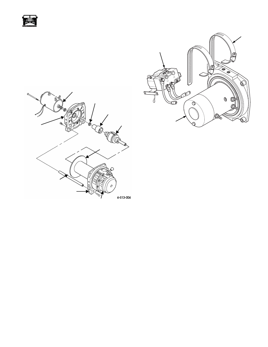
Figure 9-202: Drum Assembly and Gear
Train Assembly
21. Install brake drive and spacer to motor shaft.
22. Install motor end drum support on drum assembly.
23. Install motor on motor end drum support, ensuring to
engage brake drive with brake shaft end.
24. Install three tie rods between drum supports and secure
with six bolts. Tighten bolts to 18 lb-ft (24 N•m).
Figure 9-203: Control Unit and Motor
25. Connect three control leads to terminals and secure with
nuts (Figure 9-204).
26. Secure control to motor with clamps (Figure 9-203).
27. Install winch assembly and winch cable.
Winch Electric Thermal Switch/Brush
Assembly Replacement
Removal
1.
Remove winch and winch cable.
NOTE:
Tag leads for assembly.
2.
Remove three nuts and control leads from motor
(Figure 9-204).
3.
Loosen clamps and remove control from motor
(Figure 9-205).
MOTOR, 12 VDC
SHOWN WITHOUT CONTROL
SPACER (2)
DRUM SUPPORT
BRAKE
BRAKE
DRUM
ASSEMBLY
DRIVER
MOTOR END
DRUM SUPPORT
MOTOR END
TIE ROD
GEAR TRAIN
ASSEMBLY
00-S13-006
CONTROL
CLAMP
MOTOR
9-86
Axles, Suspension, and Frame
_________________________________________
®
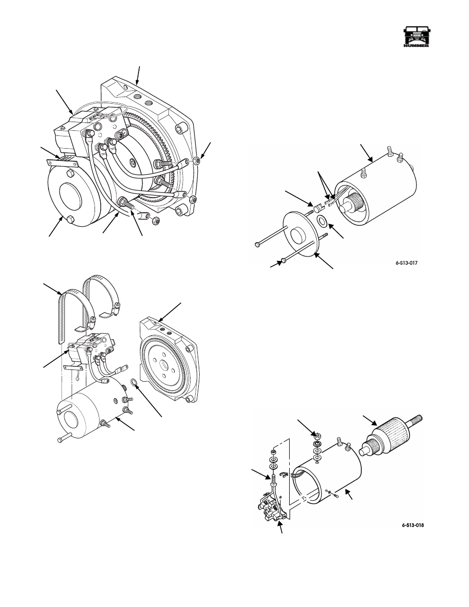
Figure 9-204: Control Leads
Figure 9-205: Control Unit and Motor
4.
Remove clamps from motor.
5.
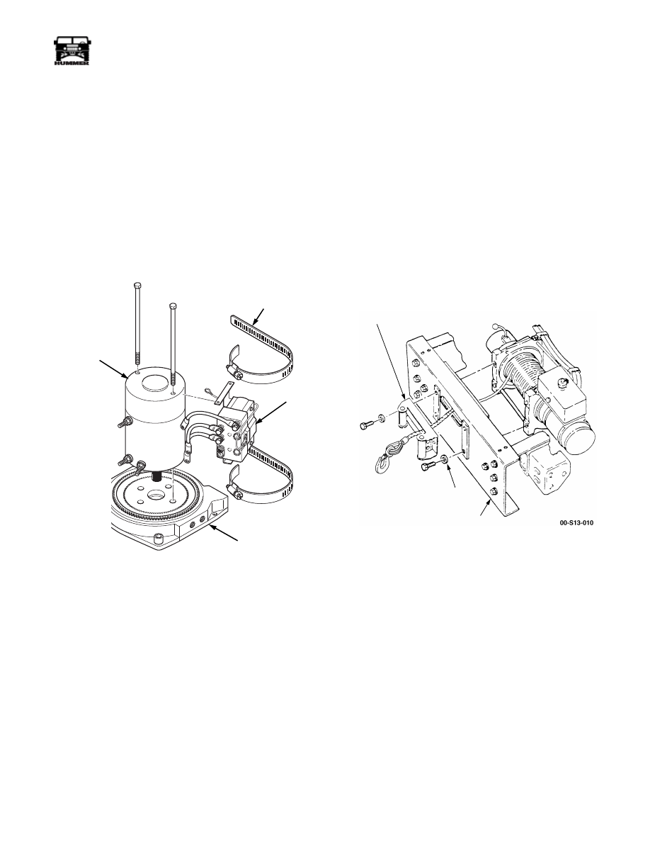
Place winch on end with motor end up (Figure 9-208).
6.
Remove two bolt assemblies and rear cover from motor
housing.
NOTE:
Perform steps 7 through 11 only if replacing brush as-
sembly.
7.
Remove electric thermal switch from two electric thermal
switch leads.
8.
Remove motor housing from drum support and armature
assembly from brush assembly (Figure 9-207).
9.
Remove nut, lockwasher, washer, and insulator securing
brush assembly power stud to motor housing. Discard
lockwasher.
10. Remove three nuts, screws, and brush assembly from
motor housing.
11. Remove spacer, insulator, and washer from brush
assembly power stud.
Figure 9-206: Motor and Gasket
Installation
NOTE:
Do not apply coating to any electrical contacts of the
armature assembly. Perform steps 1 through 5 only if replacing
brush assembly.
1.
Install washer, insulator, and spacer on brush assembly
power stud (Figure 9-207).
2.
Install brush assembly in motor housing with three screws
and nuts
.
Figure 9-207: Brush Assembly and Armature
Assembly
00-S13-005
CLAMP
DRUM SUPPORT
NUT
MOTOR
CONTROL
LEAD
TERMINAL
CONTROL
00-S13-009
MOTOR
CLAMP
SPACER
DRUM SUPPORT
CONTROL
REAR COVER
SPACER
ELECTRIC THERMAL
SWITCH
ELECTRIC THERMAL
SWITCH LEADS
MOTOR
HOUSING
BOLT
ASSEMBLY
SPACER
MOTOR
HOUSING
ARMATURE
ASSEMBLY
BRUSH
BRUSH
POWER
ASSEMBLY
ASSEMBLY
STUD
________________________________________
Axles, Suspension, and Frame 9-87
®
05745159
3.
Secure brush assembly power stud to motor housing with
insulator, washer, lockwasher, and nut.
4.
Coat armature shaft with lubricant and install in brush
assembly.
5.
Coat head of electric thermal switch with lubricant and
connect to two electric thermal switch leads
(Figure 9-206).
6.
Position spacer in drum support, and install rear cover on
motor housing.
7.
Install motor on drum support ensuring to engage motor
shaft into brake drum.
8.
Secure motor to motor end drum support with two bolt
assemblies. Tighten hex-head bolt to 60-70 lb-in. (7-8
N•m) (Figure 9-208).
Figure 9-208: Control Unit and Motor
9.
Install clamps on motor.
10. Install control on motor.
11. Connect three control leads to terminals and secure with
nuts (Figure 9-204).
12. Secure control to motor with clamps.
13. Install winch assembly and winch cable.
Winch Roller Fairlead (Option)
Replacement
The winch roller fairlead provides greater functional versatil-
ity. The winch cable can be routed at much sharper angles
since the fairlead rollers will keep it from binding on the
bumper edges.
Removal
WARNING: To avoid injury or damage, support winch
during removal.
1.
Remove circlips on one vertical and one horizontal roller.
2.
Remove one vertical and one horizontal roller.
3.
Remove washers, bolts, and the roller fairlead from the
front bumper (Figure 9-209).
Figure 9-209: Winch Fairlead
Installation
1.
Place the winch cable and hook assembly through the
roller fairlead and install the fairlead on the front bumper
with washers and bolts. Tighten bolts to 60 lb-ft (81 N•m)
(Figure 9-209).
2.
Install the horizontal and vertical rollers and circlips.
00-S13-008
MOTOR
MOTOR END
DRUM SUPPORT
CLAMP
CONTROL
FAIRLEAD
WASHER
FRONT
BUMPER
9-88
Axles, Suspension, and Frame
_________________________________________
®
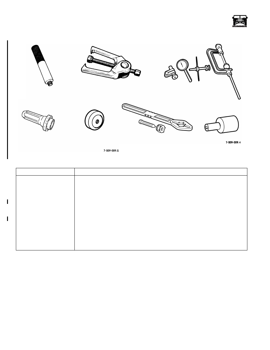
ESSENTIAL TOOLS
Procure from Kent-Moore.
TOOL
DESCRIPTION
J–8092
Universal Driver Handle
J–24319-B
Steering Linkage and Tie Rod Puller
J–8001
Dial Indicator
J–29162
Rear Retainer Seal Installer
J–44905
Input Seal Installer
J–8614-O1
Yoke Holding Tool (includes J–8614-5 bolt kit)
J–42545
Clampnut Socket
J–44906
Spindle Seal Installer (not shown)
J–38869
Seal Installer (not shown)
J–35910
Axle Boot Crimping Tool (not shown)
J–42546
1/4 in. Drive Torque Wrench (Preset) (not shown)
J–42547
3/8 in. Drive Torque Wrench (Preset) (not shown)
J–42591
Steering Cover Seal Installer (not shown)
J–29162
J–44905
J–24319-B
J–8001
J–42545
J–8092
J–8614-O1
3-1-01
Нет комментариевНе стесняйтесь поделиться с нами вашим ценным мнением.
Текст