Hummer H1 (2002+). Manual — part 155
________________________________________
Axles, Suspension, and Frame 9-81
®
05745159
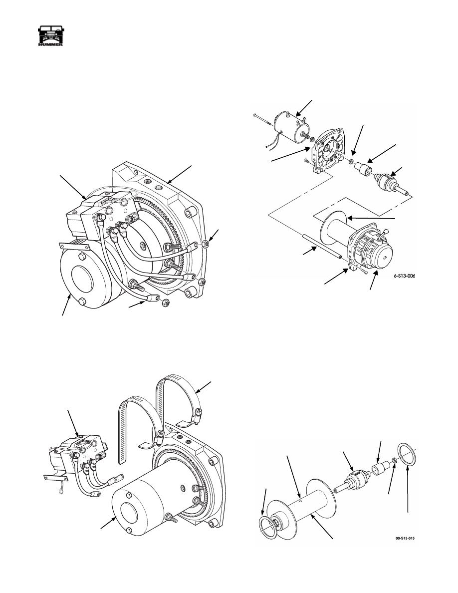
Winch Assembly Repair
Disassembly
1.
Remove winch and winch cable.
NOTE:
Tag leads for assembly.
2.
Remove three nuts and control leads from motor
(Figure 9-188).
Figure 9-188: Control Leads
3.
Loosen clamps and remove control from motor
(Figure 9-189).
Figure 9-189: Control Unit
4.
Remove clamps from motor.
5.
Mark motor end drum support, gear train assembly, and
gear end drum support for assembly (Figure 9-190).
Figure 9-190: Drum Support and
Gear Train Assembly
6.
Remove six bolts, three tie rods and gear end drum support
from winch.
7.
Remove motor, and motor end drum support from drum
assembly.
8.
Remove motor brake driver and spacer from motor shaft.
9.
Remove drum assembly from gear train assembly
(Figure 9-190).
10. Remove two nylon thrust washers from drum
(Figure 9-191).
Figure 9-191: Thrust Washers and Brake
00-S13-005
LEAD
CONTROL
DRUM SUPPORT
NUT
MOTOR
00-S13-006
CONTROL
CLAMP
MOTOR
MOTOR
(SHOWN WITHOUT CONTROL)
SPACER (2)
DRUM SUPPORT
BRAKE
BRAKE
DRUM
ASSEMBLY
DRIVER
MOTOR END
DRUM SUPPORT
GEAR END
TIE ROD
GEAR TRAIN
ASSEMBLY
NYLON THRUST
WASHER
BRAKE
DRUM
NYLON THRUST
WASHER
SET SCREW
BRAKE RETENTION
NOT REMOVABLE
ASSEMBLY
SPACER
BRAKE
DRIVER

9-82
Axles, Suspension, and Frame
_________________________________________
®
11. Loosen set screw that retains brake.
12. Push brake through open end of drum and remove
(Figure 9-191).
13. Remove driveshaft from gear train assembly
(Figure 9-192).
14. Turn gear train assembly over with gear end drum support
down. Remove ten hex-head screws and gear housing
from gear end drum support.
15. Remove gasket from gear end drum support. Discard
gasket (Figure 9-192).
Figure 9-192: Gear Train Assembly
16. Remove detent spacer, spring, and detent ball from gear
housing (Figure 9-193).
Figure 9-193: Gear Housing
17. Remove clutch lever and O-ring seal from gear housing.
Discard O-ring seal.
18. Remove two retaining rings from gear housing
(Figure 9-193).
NOTE:
Intermediate ring gear comes out with 85 to 87 steel
balls. Be sure to catch all 85 to 87 steel balls.
19. Remove intermediate ring gear and 85 to 87 steel balls
from gear housing.
20. Remove input and intermediate gear carrier assembly from
gear housing (Figure 9-193).
21. Remove and output gear carrier from output ring gear and
gear end drum support (Figure 9-194)
.
Figure 9-194: Gear Carriers
22. Remove output ring gear and gasket from gear end drum
support.
Cleaning
CAUTION: To avoid damage to equipment, do not clean brake
assembly. Clean and inspect all winch components. Replace
defective parts.
GEAR TRAIN ASSEMBLY
GASKET
GEAR HOUSING
DRIVESHAFT
GEAR END
DRUM SUPPORT
O-RING
CLUTCH
LEVER
DETENT
BALL
SPRING
DETENT
SPACER
STEEL BALLS
GEAR
RETAINING
RINGS
INTERMEDIATE
RING
GEAR
SUN
INPUT
CARRIER
GEAR
HOUSING
INTERMEDIATE
GEAR
CARRIER
INTERMEDIATE
GEAR CARRIER
OUTPUT
RING GEAR
GASKET
GEAR END
DRUM SUPPORT

________________________________________
Axles, Suspension, and Frame 9-83
®
05745159
Inspection
1.
Inspect drum for damage to splined end flanges and tube
(Figure 9-195). Replace winch if damaged.
Figure 9-195: Drum Assembly and Gear Housing
Assembly
2.
Inspect gear end and motor end drum supports for damage.
Replace if damaged.
3.
Inspect gear housing for damage. Replace if damaged.
4.
Inspect thrust plate for damage or wear. Replace if
damaged or worn. Apply grease on thrust plate for
assembly.
5.
Inspect clutch lever and driveshaft for damage. Replace if
damaged.
6.
Inspect gear teeth and machined surfaces of intermediate
ring gear for damage. Replace if damaged.
7.
Inspect gear teeth, splines, and machined surfaces of
output ring gear, output gear carrier, intermediate gear
carrier, and input gear carrier assembly for damage.
Replace any damaged parts (Figure 9-196).
Figure 9-196: Gear Carriers
8.
Inspect brake assembly for damage (Figure 9-201).
9.
Inspect motor, spline, mating surface, and terminals for
damage. Replace motor if damaged (Figure 9-197).
Figure 9-197: Motor and Control Unit
10. Inspect cover for damage. Replace if damaged.
11. Inspect control for damaged leads and damaged mounting
base. Replace control if damaged.
MOTOR END
DRUM SUPPORT
DRUM
GEAR END
DRUM SUPPORT
DRIVE
SHAFT
GEAR
HOUSING
GASKET
THRUST
WASHER
THRUST
WASHER
OUTPUT
RING GEAR
OUTPUT
GEAR CARRIER
INTERMEDIATE
GEAR CARRIER
INPUT
GEAR CARRIER
ASSEMBLY
ASSEMBLY
(THIRD STAGE)
ASSEMBLY
(SECOND STAGE)
(FIRST STAGE)
SUN
GEAR
00-S13-007
COVER
LEAD
CONTROL
SPLINE
MOTOR
DRUM
SUPPORT
SPACER
CLAMP
3-1-01

9-84
Axles, Suspension, and Frame
_________________________________________
®
Assembly
1.
Position 85 to 87 steel balls in groove of intermediate ring
gear and install intermediate ring gear in gear housing
(Figure 9-198).
Figure 9-198: Intermediate Ring Gear and
Gear Housing
2.
Install retaining rings in gear housing.
3.
Apply light oil to steel balls through the clutch lever hole.
4.
Apply grease to clutch lever hole and install O-ring seal
and clutch lever in gear housing.
5.
Install detent ball, spring, and detent spacer in gear
housing.
6.
Apply aircraft grease to output gear carrier, intermediate
gear carrier, and input gear carrier assembly (Figure 9-199).
Figure 9-199: Gear Carriers
7.
Install input gear carrier assembly in gear housing.
NOTE:
Be sure ring gear engages in gear housing.
8.
Install gasket and output ring gear on gear housing.
9.
Install intermediate gear carrier on gear housing.
10. Install output gear carrier on intermediate gear carrier.
11. Install gasket on output ring gear (Figure 9-174).
Figure 9-200: Gear Train Assembly
NOTE:
Ensure spline on drum support engages in output ring
gear.
12. Install gear end drum support on output ring gear and gear
housing.
13. Secure gear housing assembly to drum support with ten
socket-head cap screws. Tighten hex-head screws to 100
lb-in. (11 N•m).
14. Turn gear train assembly over with drum support facing
up.
15. Install driveshaft in gear train assembly (Figure 9-200).
16. Apply grease to drum bushings, seals, and output spline.
Figure 9-201: Thrust Washers and Brakes
O- RING
CLUTCH
LEVER
DETENT
BALL
SPRING
DETENT
SPACER
INTERMEDIATE
RING GEAR
RETAINING
RING
STEEL
BALLS
GEAR
HOUSING
SEAL
OUTPUT
GEAR
OUTPUT
RING GEAR
INTERMEDIATE
GEAR CARRIER
GASKET
INPUT
GEAR CARRIER
ASSEMBLY
GEAR
HOUSING
SUN
GEAR
CARRIER
GEAR TRAIN
ASSEMBLY
GASKET
DRIVE
SHAFT
GEAR END
DRUM SUPPORT
OUTPUT
RING GEAR
GEAR
HOUSING
NYLON THRUST
WASHER
BRAKE
DRUM
NYLON THRUST
WASHER
SET SCREW
BRAKE RETENSION
NOT REMOVABLE
TOLERANCE
RING
ASSEMBLY
Нет комментариевНе стесняйтесь поделиться с нами вашим ценным мнением.
Текст