Hummer H1 (2002+). Manual — part 154
________________________________________
Axles, Suspension, and Frame 9-77
®
05745159
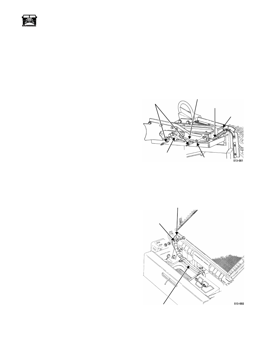
Figure 9-178: Control Leads
Figure 9-179: Control Unit and Motor
4.
Remove clamp from motor.
5.
Place winch on end with motor end up (Figure 9-180).
6.
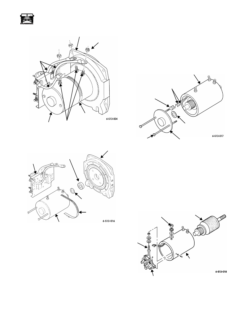
Remove two bolt assemblies and rear cover from motor
housing.
NOTE:
Perform steps 7 through 11 only if replacing brush as-
sembly.
7.
Remove electric thermal switch from two electric thermal
switch leads.
8.
Remove motor housing from drum support and armature
assembly from brush assembly (Figure 9-181).
9.
Remove nut, lockwasher, washer, and insulator securing
brush assembly power stud to motor housing. Discard
lockwasher.
10. Remove three nuts, screws, and brush assembly from
motor housing.
11. Remove spacer, insulator, and washer from brush
assembly power stud.
Figure 9-180: Motor and Gasket
Installation
NOTE:
Do not apply coating to any electrical contacts of the
armature assembly. Perform steps 1 through 5 only if replacing
brush assembly.
1.
Install washer, insulator, and spacer on brush assembly
power stud (Figure 9-181).
2.
Install brush assembly in motor housing with three screws
and nuts
.
Figure 9-181: Brush Assembly and Armature
Assembly
CLAMP
DRUM SUPPORT
NUT
MOTOR
CONTROL
LEADS
TERMINALS
MOTOR
CLAMP
SPACER
BALL BEARING
DRUM SUPPORT
CONTROL
REAR COVER
SPACER
ELECTRIC THERMAL
SWITCH
ELECTRIC THERMAL
SWITCH LEADS
MOTOR
HOUSING
BOLT
ASSEMBLY
SPACER
MOTOR
HOUSING
ARMATURE
ASSEMBLY
BRUSH
BRUSH
POWER
ASSEMBLY
ASSEMBLY
STUD
9-78
Axles, Suspension, and Frame
_________________________________________
®
3.
Secure brush assembly power stud to motor housing with
insulator, washer, lockwasher, and nut.
4.
Coat armature shaft with lubricant and install in brush
assembly.
5.
Coat head of electric thermal switch with lubricant and
connect to two electric thermal switch leads
(Figure 9-180).
6.
Position spacer over bearing on drum support, and install
rear cover on motor housing.
7.
Install motor on drum support ensuring to engage motor
shaft into brake drum.
8.
Secure motor to motor end drum support with two bolt
assemblies. Tighten hex-head bolt to 60-70 lb-in. (7-8
N•m) (Figure 9-182).
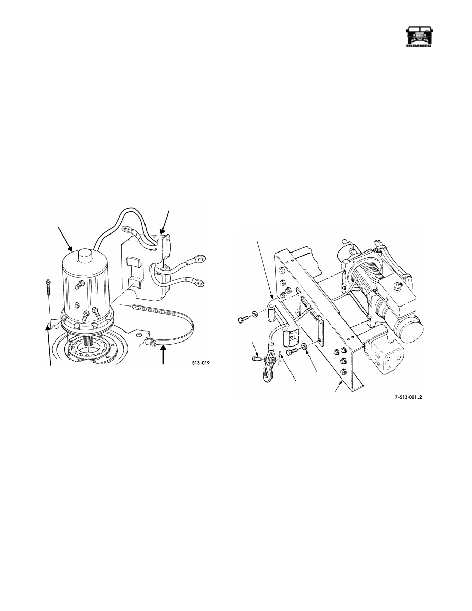
Figure 9-182: Control Unit and Motor
NOTE:
If motor or control have been pre-coated with sealing
compound, remove compound from between motor and con-
trol mounting gear contact area. Failure to do so may cause im-
proper grounding or control.
9.
Install clamp on motor.
10. Install control on motor.
11. Connect three control leads to terminals and secure with
nuts (Figure 9-178).
12. Secure control to motor with clamp.
13. Re-coat motor end of winch (including all leads and
terminals) with PlastiDip Coating or equivalent
waterproofing compound.
14. Install winch assembly and winch cable.
Winch Roller Fairlead (Option)
Replacement
The winch roller fairlead provides greater functional versatil-
ity. The winch cable can be routed at much sharper angles
since the fairlead rollers will keep it from binding on the
bumper edges.
Removal
WARNING: To avoid injury or damage, support winch
during removal.
1.
Remove the cotter pin, hook retainer pin and hook from
the winch cable.
2.
Remove washers, bolts, and the roller fairlead from the
front bumper (Figure 9-183).
Figure 9-183: Winch Fairlead
Installation
1.
Install the fairlead on the front bumper with washers and
bolts. Tighten bolts to 60 lb-ft (81 N•m) (Figure 9-183).
2.
Install the hook, the hook retainer pin and the cotter pin on
the winch cable.
MOTOR
MOTOR END
DRUM SUPPORT
CLAMP
CONTROL
FAIRLEAD
WASHER
FRONT
BUMPER
COTTER
PIN
HOOK
PIN
________________________________________
Axles, Suspension, and Frame 9-79
®
05745159
WINCH (OPTION) VIN 186477 AND LATER
NOTE:
Individual parts may not be available for some of the
following repair procedures. Assemblies must be used in place
of individual parts. Check for parts availability before disas-
sembly.
Winch Troubleshooting
Winch Inoperative
1.
Check for jammed winch cable.
2.
Check winch control cable connector for corrosion or
loose connection. Clean corroded connector or secure
loose connection.
3.
Check for loose or damaged winch power cables. Using
voltmeter, connect positive meter lead to positive power
cable (red) at the winch motor, and negative meter lead to
the winch motor ground cables (black). If voltage is not
present, repair or replace winch power cables.
4.
Disconnect winch control from winch. Using an
ohmmeter, check for continuity between the common
terminal and the other two terminals on winch control
cable connector. Check for continuity one at a time, while
holding control in the OUT position and the IN position. If
continuity is present in both positions, repair winch. If
continuity is not present in both positions, replace winch
control.
Winch Replacement
Removal
WARNING: To avoid personal injury or damage, sup-
port winch during removal.
1.
Disconnect battery ground cables (Section 12).
2.
Remove two battery cable bolts, battery cables, and winch
cables from battery (Figure 9-158).
Figure 9-184: Winch Cables On Battery
3.
Remove nut, lockwasher, capscrew, and clamp from right
frame extension. Discard lockwasher. Pull winch cables
through the splash shield to front of vehicle
(Figure 9-185).
Figure 9-185: Frame Bracket
POSITIVE
BATTERY
NEGATIVE
POSITIVE
BATTERY CABLE
BATTERY
CABLE
WINCH
CABLE
NEGATIVE
WINCH CABLE
BATTERY CABLE
BOLTS
CLAMP
FRAME BRACKET
POWER CABLES
9-80
Axles, Suspension, and Frame
_________________________________________
®
4.
Remove four nuts, washers, bolts, and winch from front
bumper (Figure 9-186).
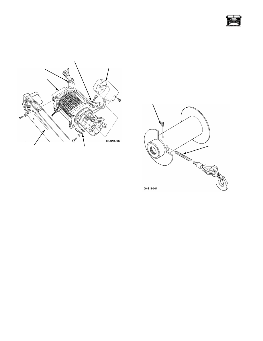
Figure 9-186: Winch and Winch Cables
5.
Remove two bolts and clamps securing winch cables to
winch.
6.
Remove bolt and control box cover from winch.
7.
Remove capscrew, washer, and negative winch cable from
winch.
8.
Remove bolt and positive winch cable from winch.
Installation
1.
Install positive winch cable on winch with bolt
(Figure 9-186).
2.
Install negative winch cable on winch with washer and
capscrew.
3.
Coat motor end of winch with coating compound.
4.
Install control box cover on winch with bolt.
5.
Secure two winch cables to winch with two clamps and
bolts.
6.
Install winch on front bumper with four washers, bolts,
and nuts. Tighten bolts to 60 lb-ft (81 N•m).
7.
Route winch power cables through the splash shield.
8.
Install winch cables on frame bracket with clamp,
capscrew, lockwasher, and nut (Figure 9-185).
9.
Connect battery ground cables (Section 12).
Winch Cable Replacement
WARNING: To avoid injury, wear gloves when han-
dling winch cable.
Removal
1.
Unwind winch cable.
2.
Remove set screw and winch cable/hook assembly from
drum assembly (Figure 9-187).
Figure 9-187: Winch Cable
Installation
3.
Install winch cable/hook assembly on drum assembly with
set screw.
CAUTION: Install winch cable on drum under a load of at
least 500 lb (227 kg), or outer wraps will draw into
inner wraps and damage cable.
NOTE:
Spool winch cable according to rotation label on
winch or brake will not function.
4.
Rewind and lubricate winch cable.
CLAMP
POSITIVE
CONTROL
NEGATIVE
FRONT BUMPER
WINCH
BOX
COVER
WINCH
CABLE
WINCH
CABLE
SET SCREW
CABLE ANCHOR
CABLE/HOOK
ASSEMBLY
Нет комментариевНе стесняйтесь поделиться с нами вашим ценным мнением.
Текст