Hummer H1 (2002+). Manual — part 212
____________________________________________________
Electrical System 12-74.1
®
05745159
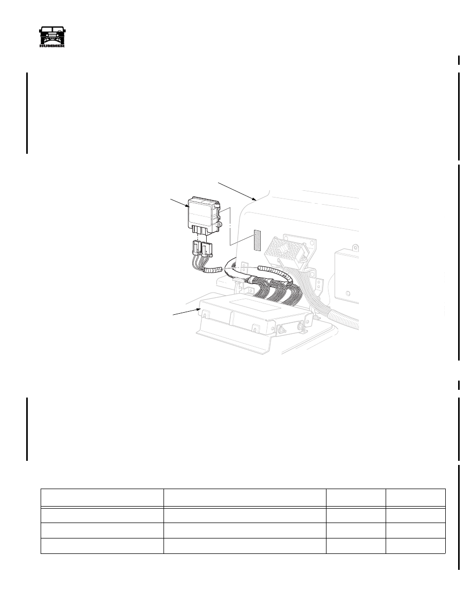
Digital Ratio Adapter
Location
The digital ratio adapter is located under the center console on
the engine cover, just above the powertrain control module.
Removal
1.
Remove the cup holder from the center console.
2.
Disconnect the two harness connectors from the digital
ratio adapter.
3.
Pull the digital ratio adapter off of the hook and loop and
remove from the center console.
Installation
1.
Install the digital ratio adapter in the center console on the
hook and loop.
2.
Connect the harness connectors to the bottom of the digital
ratio adapter.
3.
Install the cup holder in the center console.
Figure 12-93.1 Digital Ratio Adapter Removal
√
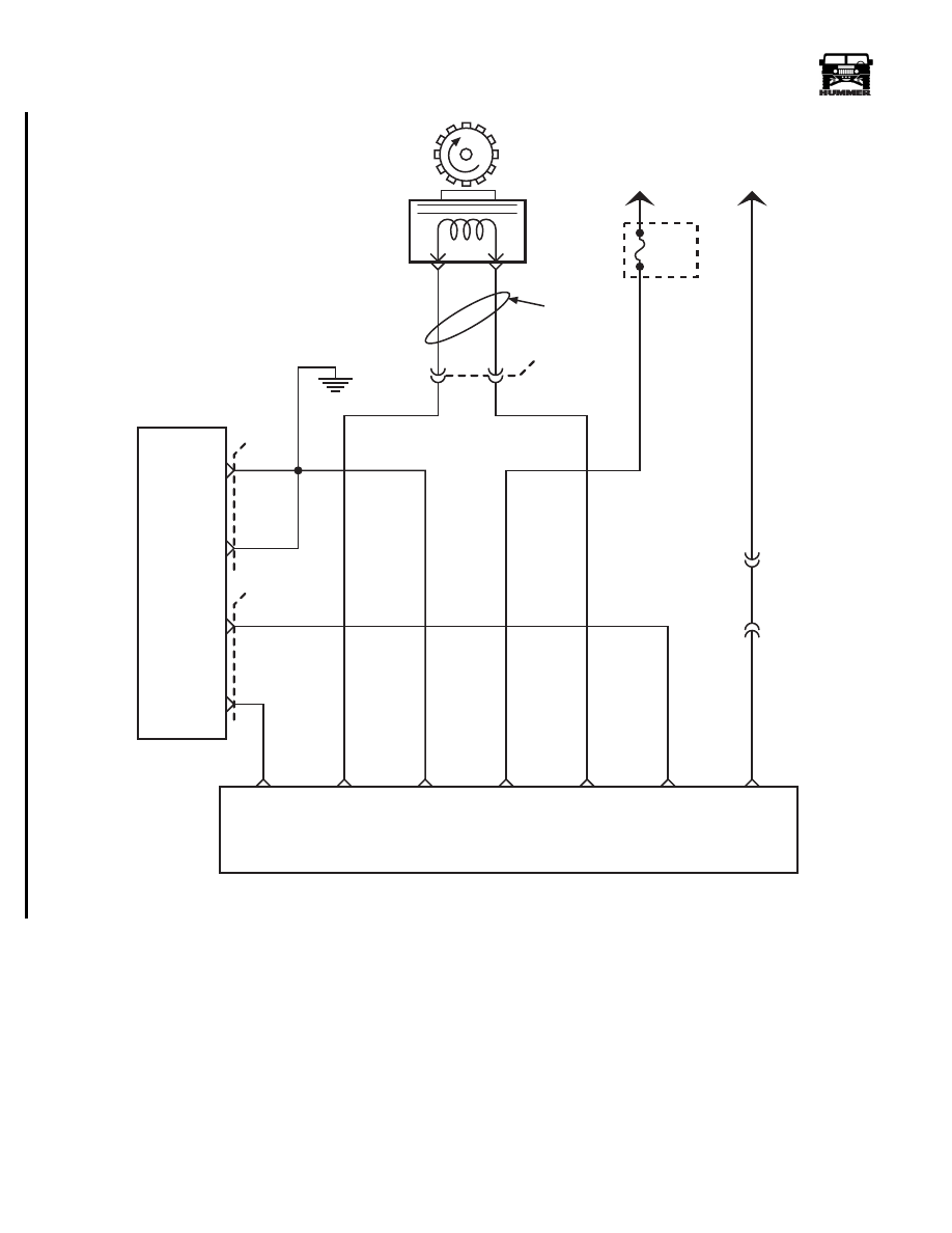
Circuit Description
The speed sensor circuit consists of a magnetic induction type
sensor, a Digital Ratio Adapter (DRA) and wiring. Geared
teeth pressed on the output shaft induce an alternating current
in the sensor. This A/C signal is transmitted to the DRA. The
DRA compensates for various axle ratios and converts the sig-
nal into a digital signals for use by the speedometer, cruise
control, and the PCM. The DRA sends two different signal to
the PCM. Circuit 565 sends a signal of 40 pulses per revolution
of the output shaft to the PCM. This signal is used to control
shift points, line pressure, TCC and diagnostic codes. Circuit
223 sends a signal of 4000 pulses per mile to the PCM. This
signal is used for cruise and DTCs. The DRA sends a separate
signal to the speedometer on circuit 353. This signal is a
128,000 pulse per mile signal.
NOTE:
The above table only applies to 2000 model year vehicles.
01-S12-017
DIGITAL
RATIO
ADAPTER
POWERTRAIN
CONTROL
UNIT
ENGINE
COVER
Digital Ratio Adapter Out Put Signal to Speedometer
Approximate Reading
Input
Ascending
Descending
30 MPH
1066.6 Htz
X
60 MPH
2133.3 Htz
X
30 MPH
1066.6 Htz
X
3-1-01
Section 12 Electrical System
12-74.2
Electrical System
_____________________________________________________
®
Figure 12-93.2 Digital Ratio Adapter Wiring Diagram
TWISTED
PAIR
VEHICLE
SPEED
SENSOR
(VSS)
B
A
GROUND
VEHICLE
SPEED
SENSOR
RETURN
4
679 LG
VEHICLE
SPEED
DIGITAL RATIO ADAPTER
CRUISE
CONTROL
REFERENCE
SIGNAL
4000 PPM
SPEEDO
REFERENCE
SIGNAL
00-S12-038
+12 VOLT
IGNITION
SIGNAL
OUTPUT SHAFT
REVOLUTION
SIGNAL
7
8
9
12
13
10
A6
570 BK
POWERTRAIN
CONTROL
MODULE
( PCM )
GROUND
GROUND
4000 PPM
CRUISE
CONTROL
REFERENCE
SIGNAL
A7
D6
D9
570 BK
565 BR
C29
C28
FUSE
1D
15 AMP
570 BR
239 PK
676 PP
565 BR
353 YL
G2
TO
IGNITION
EXTERIOR
FUSE
BOX
C1-18
C3-P9
TO
SPEEDO
B
A
C33
223 DB
40 PULSE
OUTPUT SHAFT
REVOLUTION
SIGNAL
TO PCM
3-1-01

______________________________________________________
Electrical System 12-75
®
05745159
HVAC Main Blower Inoperative ALL BUT High
Step
Action
Value(s)
Yes
No
1
Ignition on, blower switch set to Med2, mode dial
set to face. Measure voltage on the yellow
wire(CKT754) at the blower relay. Is voltage
present?
8 -10v
Replace the
blower relay.
Go to step 2.
2
Ignition on, blower switch set to Med2, mode dial
set to face. Measure voltage on the grey
wire(CKT752) at the blower resistor. Is voltage
present?
12v
Replace blower
resistor.
Go to step 3.
3
Ignition on, blower switch set to Med2, mode dial
set to face. Measure voltage on the grey
wire(CKT752) at pin C of the 8pin connector on
the back of the HVAC control head. Is voltage
present?
12v
Repair open,
bad connection
or short to
ground in CKTS
751, 752, and
755 between
HVAC control
head and resis-
tor block.
Replace control
head.
HVAC Compressor Inoperative
Step
Action
Value(s)
Yes
No
1
Perform On-board diagnostic system check. Is
system functioning properly?
Go to step 2.
Diagnose prob-
lem in on-board
diagnostic sys-
tem first.
2
Does A/C system have an adequate charge?
Go to step 3.
Diagnose leak
and recharge.
3
Is engine in an overheated condition?
Cool down and
recheck.
Go to step 4.
4
Connect scan tool to vehicle. Ignition on, find
misc. tests and command compressor clutch on.
Does clutch come on?
Go to step 10.
Go to step 5.
5
Disconnect the compressor clutch. Connect a test
lamp to ground, and probe the brown wire at the
clutch connector. Using the scan tool, command
the clutch on. Does the test light come on?
Replace the
compressor
clutch.
Go to step 6.
6
Remove A/C relay from the exterior fuse box.
Using a DVOM set to measure voltage, ignition
on, check for voltage at cavities 4E and 6E
(CKT400) in the exterior fuse box. Is voltage
present?
12v
Go to step 7.
Repair open,
bad connection
or short in
CKT400
between exte-
rior fuse box
and ignition
switch.
4-1-00
Section 12 Electrical System

12-76
Electrical System
_______________________________________________________
®
7
Using a DVOM set to measure voltage, place the
positive lead on a battery power source. Place the
ground lead in cavity 6F(CKT440). Using the
scan tool, command the compressor clutch on.
Does meter display battery voltage?
12v
Go to step 8.
Go to step 9.
8
Using a DVOM set to measure resistance. Check
resistance between cavity 4F(CKT348) and the
brown wire(CKT348)at the compressor clutch
connector. Is resistance below specification?
<.2
Ω
Replace com-
pressor relay.
Repair open or
bad connection
in CKT348
between clutch
relay and com-
pressor clutch.
9
Ignition on, using a DVOM set to measure volt-
age, backprobe pin D5 in C28 at the
PCM(CKT440) with the negative lead. Place the
positive lead on a battery voltage source. Using
the scan tool, command the compressor clutch on.
Does the meter display battery voltage?
12v
Repair open, or
bad connection
in CKT440
between PCM
and A/C clutch
relay.
Replace the
PCM.
10
Ignition on, locate engine data list, and “A/C
Request”. Turn mode dial on HVAC control head
to MAX A/C. Does scan tool display indicate A/C
request?
Replace PCM.
Go to step 11.
11
Ignition on, mode dial set to MAX A/C. Using a
DVOM set to measure voltage, backprobe the tan
wire(CKT198) at the temperature cutout switch
on the HVAC unit with the positive probe. Place
the negative lead on a known good ground. Is
voltage present?
12v
Go to step 14.
Go to step 1.
12
Ignition on, mode dial set to MAX A/C. Using a
DVOM set to measure voltage, backprobe the yel-
low wire(CKT347) at the temperature cutout
switch on the HVAC unit with the positive probe.
Place the negative lead on a known good ground.
Is voltage present?
12v
Replace the
temperature cut-
out switch.
Go to step 13.
13
Using a DVOM set to measure voltage, ignition
on, mode dial set to MAX A/C, backprobe for
voltage on pin H (CKT347) in the 8 wire connec-
tor at the rear of the HVAC control head. Is volt-
age present?
12v
Repair open,
bad connection
or short in
CKT347
between HVAC
control head and
temperature cut-
out switch.
Replace control
head.
HVAC Compressor Inoperative (Continued)
Step
Action
Value(s)
Yes
No
4-1-00
Нет комментариевНе стесняйтесь поделиться с нами вашим ценным мнением.
Текст