Hummer H1 (2002+). Manual — part 211
______________________________________________________
Electrical System 12-71
®
05745159
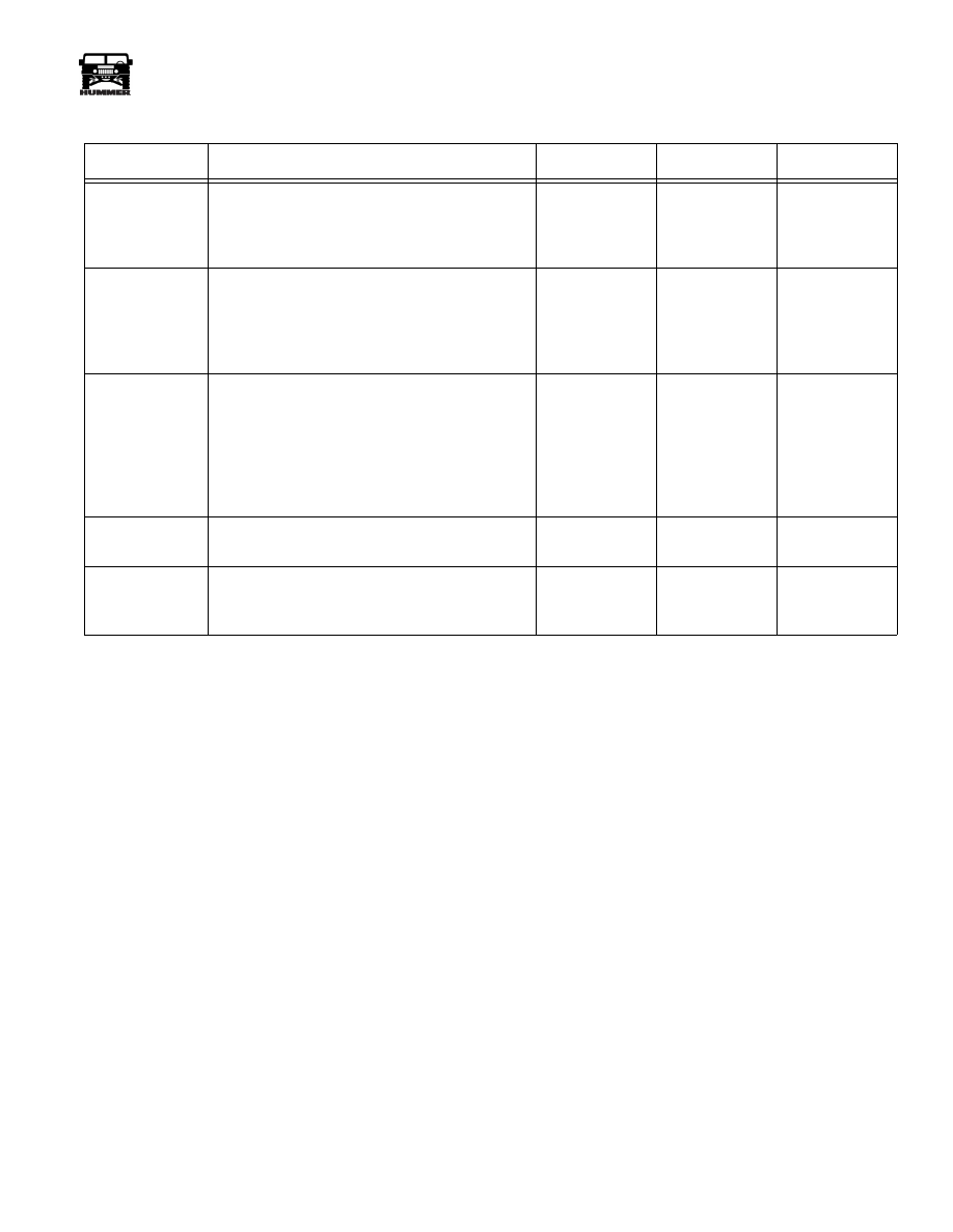
Oil Pressure Gauge Inoperative
Step
Action
Value(s)
Yes
No
1
Is gauge maxed out?
Repair open or
bad connection
in CKT31 or
gauge sending.
Go to step 2.
2
Using a DVOM set to measure voltage, check for
voltage at the rear of the oil pressure gauge on the
grey wire(CKT30) connect negative meter lead to
ground on black wire(CKT59). With ignition on,
is voltage present?
12v
Go to step 4.
Go to step 3.
3
Move the negative meter lead to a known good
ground. Is voltage present?
12v
Repair open or
bad connection
in CKT59
between oil
pressure gauge
and G4.
Repair open,
bad connection
or short in
CKT30 between
oil pressure
gauge and fuse
4B.
4
Ignition on, remove the tan wire (CKT 31) from
the oil pressure gauge. Does the gauge max out?
Go to step 5.
Replace the oil
pressure gauge.
5
Reconnect signal wire to gauge. Disconnect sig-
nal wire(CKT31) at sending unit. With ignition on
does gauge max out?
Replace send-
ing unit.
Repair short to
ground in
CKT31.
4-1-00
12-72
Electrical System
_______________________________________________________
®
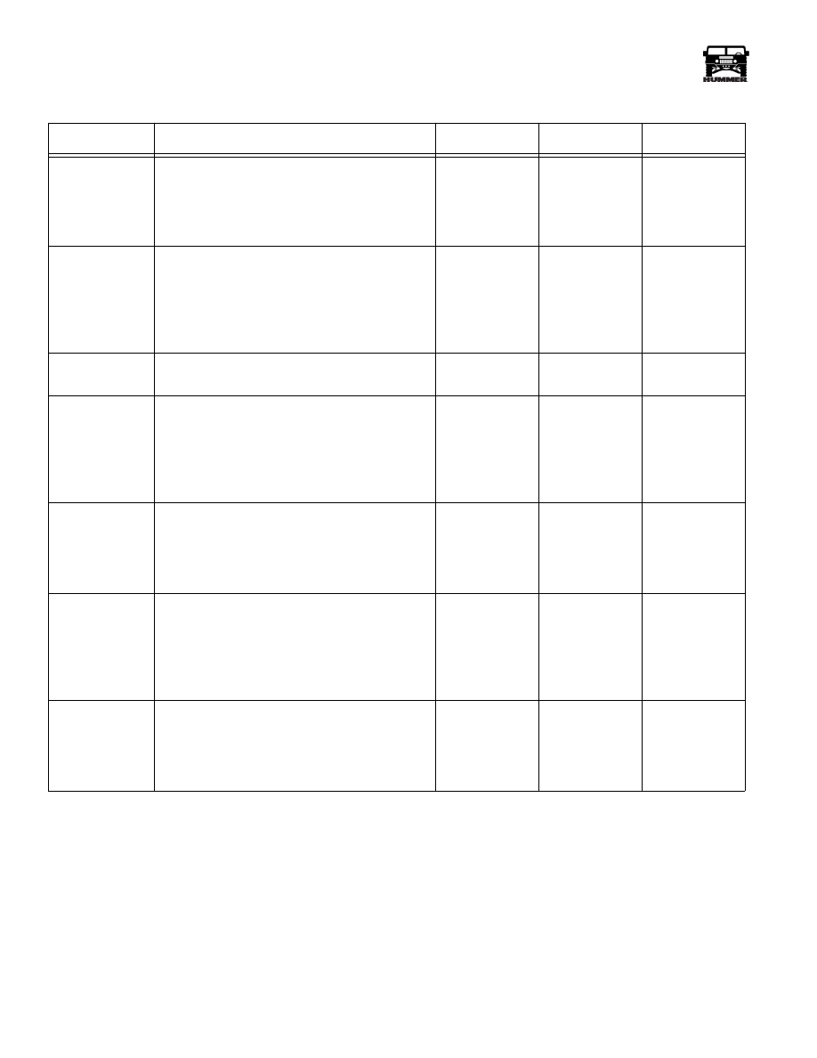
Fuel Gauge Inoperative
Step
Action
Value(s)
Yes
No
1
Using a DVOM set to measure voltage, check for
voltage at the rear of the fuel gauge on the grey
wire(CKT30) connect negative meter lead to
ground on black wire(CKT59). With ignition on,
is voltage present?
12v
Go to step 3.
Go to step 2.
2
Move the negative meter lead to a known good
ground. IS voltage present?
12v
Repair open or
bad connection
in CKT59
between fuel
gauge and G4.
Repair open,
bad connection
or short in
CKT30 between
fuel gauge and
fuse 4B.
3
With the ignition on, ground the signal lead does
the gauge go to Full?
Full
Go to step 4.
Replace gauge.
4
Disconnect fuel selector valve. Using a jumper
wire, ground the pink wire(CKT29). With the
ignition on does the fuel gauge go to full?
Full
Go to step 5.
Repair open or
bad connection
in CKT29
between fuel
gauge and fuel
selector valve?
5
Determine fuel level in the main tank. Using a
DVOM set to measure resistance, measure resis-
tance to ground on the blue wire(CKT673). Does
resistance value correspond with fuel level in
tank.
Empty=268
Ω
Half=124.4
Ω
Full=19.3
Ω
Go to step 6.
Go to step 7.
6
Determine fuel level in the auxiliary tank. Using a
DVOM set to measure resistance, measure resis-
tance to ground on the yellow wire(CKT675).
Does resistance value correspond with fuel level
in tank.
Empty=268
Ω
Half=124.4
Ω
Full=19.3
Ω
Replace fuel
selector valve.
Go to step 7.
7
Gain access to fuel level sending unit connectors.
Using a DVOM set to measure resistance, check
resistance through the sending unit. Does resis-
tance value correspond with the fuel level in the
tank?
Empty=268
Ω
Half=124.4
Ω
Full=19.3
Ω
Repair open,
bad connection
or short in CKT
673, 675, or 58.
Replace send-
ing unit.
4-1-00
______________________________________________________
Electrical System 12-73
®
05745159
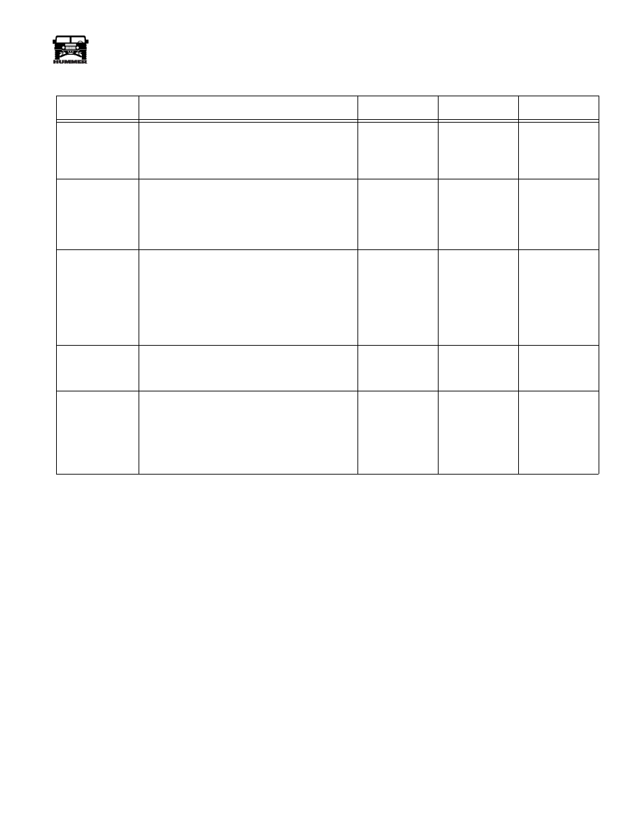
Engine Temperature Gauge Inoperative
Step
Action
Value(s)
Yes
No
1
Is gauge maxed out with ignition on?
Repair short to
ground in CKT
39 or faulty
sending unit.
Go to step 2.
2
Using a DVOM set to measure voltage, check for
voltage at the rear of the oil pressure gauge on the
grey wire(CKT39) connect negative meter lead to
ground on black wire(CKT59). With ignition on,
is voltage present?
12v
Go to step 4.
Go to step 3.
3
Move the negative meter lead to a known good
ground. Is voltage present?
12v
Repair open or
bad connection
in CKT59
between oil
pressure gauge
and G4.
Repair open,
bad connection
or short in
CKT30 between
oil pressure
gauge and fuse
4B.
4
With the ignition on, momentarily ground the
dark green wire(CKT30) at the rear of the gauge.
Does the gauge go to maximum?
Go to step 5.
Replace the
temperature
gauge.
5
With the ignition on, momentarily ground the sig-
nal wire(CKT39) at the sending unit. Does the
gauge go to maximum?
Replace the
sending unit.
Repair open, or
bad connection
in CKT39
between gauge
and sending
unit.
4-1-00
12-74
Electrical System
_______________________________________________________
®
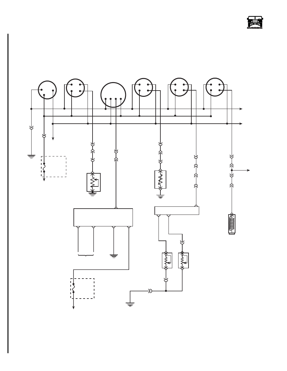
Figure 2-93: Gauges Schematic
FUSE
4B
5 AMP
INTERIOR
FUSE BOX
TO
DIMMER
SWITCH
TO IGNITION
VOLT
OIL
SPEEDO
TEMP
FUEL
G
I
L
I
G L
S
G L S
I
I
G L
S
I
G L
S
59 BK
30 GY
17 PP
G4
C3-N6
C3-N7
C3-L7
C1-30
C5-C10
G1
O I L
P R E S S U R E
S E N D E R
TO
IGN
SWITCH
31 TN
353 YL
C3-P9
C1-I8
39 DG
C3-P8
C1-36
C5-A1
29 PK
C3-P7
C1-35
C2-35
C26-B
ENGINE
TEMPERATURE
SENSOR
GAUGE
OUTPUT
FUEL
SELECTOR
VALVE
DIGITAL
RATIO
ADAPTER
(DRA)
SPEEDO
SIGNAL
SPEED SIGNAL
ENGINE
GROUND IGN+
679 LG
676 PP
570 BK
239 PK
8
9
9-S12-059.3
TO VEHICLE
SPEED SENSOR (VSS)
G2
C26-C
675 YL
A
AUX TANK
FUEL LEVEL
SENDING UNIT
MAIN TANK
FUEL LEVEL
SENDING UNIT
673 DB
58 BK
C26-A
B
C38-B
G1
G1
FUSE
3A
20 AMP
EXTERIOR
FUSE BOX
I S
TACHOMETER
G L
644 YL
C3-K9
C1-49
C5-B9
349 YL
TO CTIS
HARNESS
CRANKSHAFT
POSITION
SENSOR
TO PCM
349 YL
12
7
10
4-1-00
Нет комментариевНе стесняйтесь поделиться с нами вашим ценным мнением.
Текст