Hummer H1 (2002+). Manual — part 213
______________________________________________________
Electrical System 12-77
®
05745159
14
Ignition on, mode dial set to MAX A/C. Discon-
nect the high pressure cutout switch on the com-
pressor. Using a DVOM set to measure voltage,
check for voltage on the tan wire(CKT198). Is
voltage present?
12v
Go to step 15.
Repair open,
bad connection,
or short in
CKT198
between tem-
perature cutout
switch and high
pressure cutout
switch.
15
Using a DVOM set to measure resistance, check
continuity across the two pins on the high pres-
sure cutout switch. Is resistance below specifica-
tion?
<.2
Ω
Go to step 16.
Replace the
high pressure
cutout switch.
16
Ambient temperature above 45°. Disconnect the
ambient temperature switch. Using a DVOM set
to measure resistance, measure continuity across
the ambient temperature switch terminals. Is
resistance below specification?
<.2
Ω
Go to step 17.
Replace ambi-
ent temperature
switch.
17
Disconnect low pressure cutout switch. Using a
DVOM set to measure resistance, measure conti-
nuity across the low pressure cutout switch. Is
resistance below specification?
<.2
Ω
Repair open,
bad connection
or short in
CKT439
between high
pressure cutoff
switch and
PCM.
Replace the low
pressure cutout
switch.
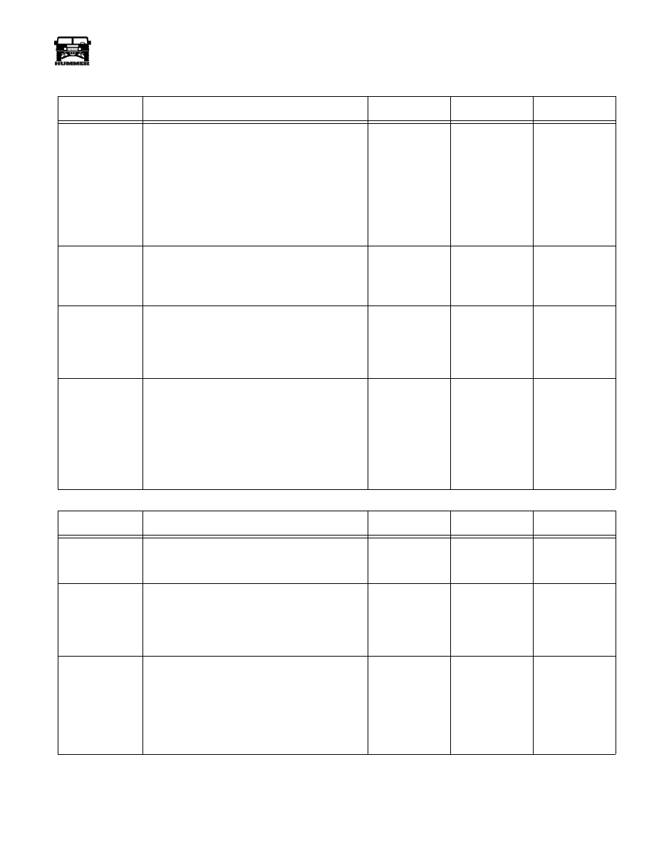
HVAC Temperature Door Inoperative
Step
Action
Value(s)
Yes
No
1
With the ignition switch in the run position, oper-
ate temperature control dial and observe the
motor. Does door move?
Condition is
intermittent.
Go to step 2.
2
Remove the temperature blend door motor from
the side of the HVAC case. With the ignition
switch in the run position, operate the temperature
control dial and observe the motor. Is the motor
turning?
Mechanical
problem in the
HVAC case.
Go to step 4.
3
Disconnect electrical connector from the temper-
ature blend door motor. Using a DVOM set to
measure voltage, and using J–35616-92 test
adapters, probe the GN wire (CKT 399) with the
positive lead and the BK wire (CKT 58) with the
negative lead. Turn the ignition switch to the run
position. Is voltage present?
12v
Go to step 6.
Go to step 4.
HVAC Compressor Inoperative (Continued)
Step
Action
Value(s)
Yes
No
4-1-00

12-78
Electrical System
_______________________________________________________
®
4
With ignition on, using a DVOM set to measure
voltage and using J–35616-92 test adapters probe
the GN wire (CKT 399) with the positive lead.
Place the negative lead on a known good ground.
Is voltage present?
12v
Go to step 5.
Repair open or
short to ground
between tem-
perature blend
door motor and
fuse 7C.
5
With the ignition off, and using a DVOM set to
measure ohms, check for resistance between the
BK wire (CKT 58) of the temperature blend door,
and a good ground. Does resistance exceed speci-
fications?
<.2
Ω
Locate open or
bad connection
between tem-
perature blend
door motor and
G4.
Go to step 6.
6
Using a DVOM set to read volts, the ignition
switch on the run position, and using J–35616-92
test adapters, probe the blue wire (CKT 402) with
the positive lead, and the BK wire (CKT 58) with
the negative lead. Rotate temperature control dial
on the HVAC control head from cold to hot and
back. Is voltage present at the cold setting and 0v
on the hot setting?
Cold = 12v
Hot = 0v
Cold = 12v
Replace the
temperature
blend door
motor.
Go to step 7.
7
Disconnect the 8 wire connector at the HVAC
control head. Using a DVOM set to measure
ohms, check resistance between pin F (CKT 402)
of the 8 wire connector and the blue wire (CKT
402) of the temperature blend door connector.
Does resistance exceed specifications?
62K
Ω
Go to step 9.
Go to step 8.
8
Check for open or bad connection between the
HVAC control head 8 wire connection and the
temperature blend door motor connection. Check
for loose terminals at the control head. Was a bad
connection found?
Repair or
replace harness
as necessary.
Go to step 9.
9
Using a DVOM set to measure voltage, probe pin
E (CKT 399) of the 8 wire connector on the
HVAC control head with the positive lead, and
pin B (CKT 58) of the three wire HVAC control
head connector with the negative lead. With igni-
tion on, is voltage present?
12v
Replace faulty
HVAC control
head.
Go to step 10.
10
Using a DVOM set to measure voltage, probe pin
E (CKT 399) of the HVAC control head eight
wire connector with the positive lead. Attach the
negative lead to a known good ground. With the
ignition switch in the run position, is voltage
present?
12v
Go to step 11.
Locate short or
open between
the HVAC con-
trol head and
fuse 7C.
HVAC Temperature Door Inoperative (Continued)
Step
Action
Value(s)
Yes
No
4-1-00

______________________________________________________
Electrical System 12-79
®
05745159
11
Using a DVOM set to measure ohms, check resis-
tance between pin B (CKT 58) of the HVAC con-
trol head connector and a good ground. Does
resistance exceed specifications?
<.2
Ω
Replace faulty
HVAC control
head.
Locate and
repair open or
poor connec-
tion in the
ground circuit
between pin B
and G4.
HVAC Temperature Door Inoperative (Continued)
Step
Action
Value(s)
Yes
No
4-1-00
12-80
Electrical System
_______________________________________________________
®
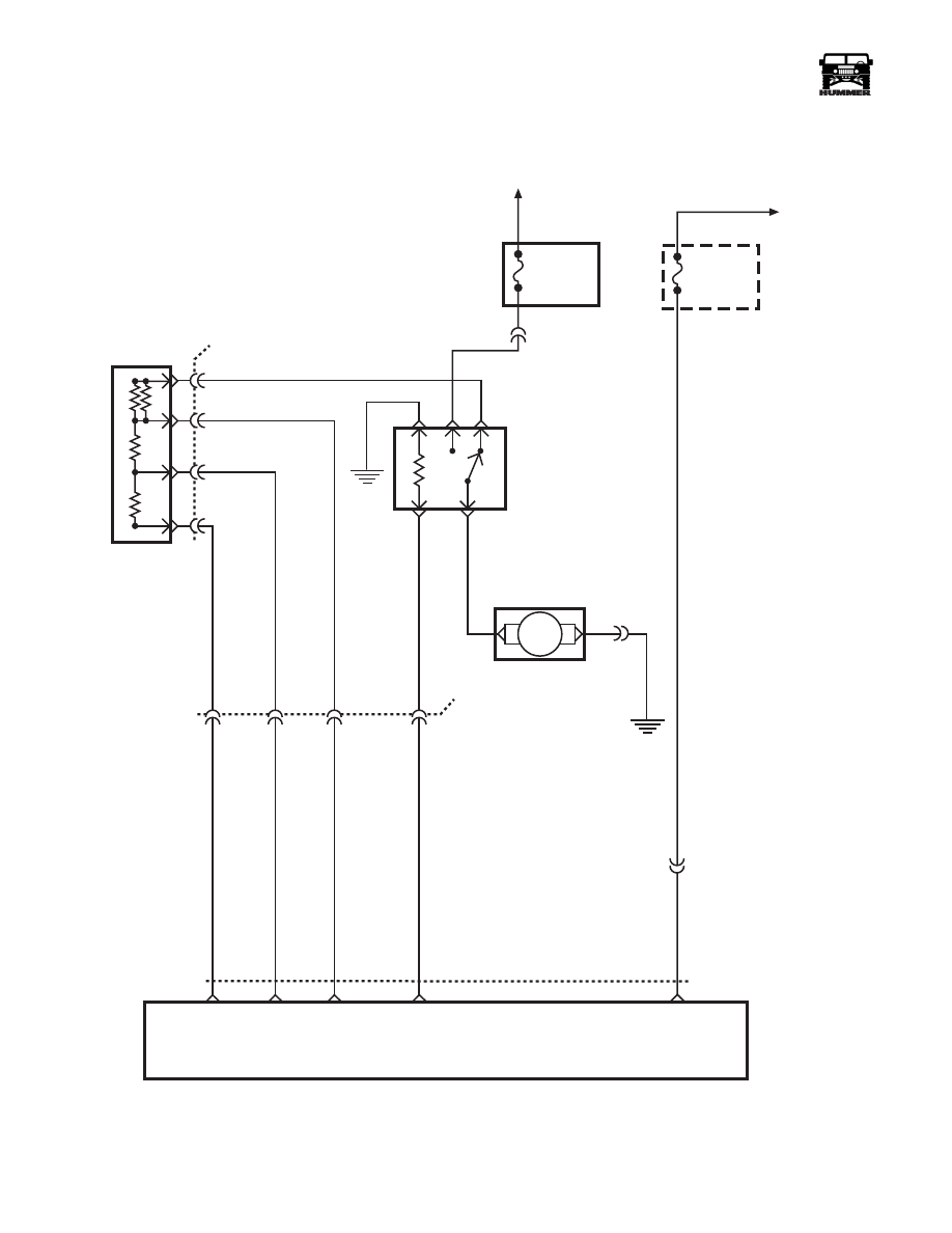
Figure 12-94: HVAC Blower Schematic
30A FUSE
BUILT IN
HARNESS
FUSE
TO ALTERNATOR
BATTERY TERMINAL
FUSE 7C
30A
INTERIOR
FUSE BOX
HOT IN RUN
AND START
M
BLOWER
RESISTOR
755 DB
751 OR
752 GY
8 PIN
A
B
C
D
HVAC
CONTROL
HEAD
754 YL
364 RD
C36-A
G4
BLOWER
RELAY
BLOWER
MOTOR
86
87
87A
85
30
371 PP
G1
C36-B
757 LB
399 DG
C6-G1
E
58 BK
9-S12-060
59 BK
LOW
BLOWER
MED 1
BLOWER
MED 2
BLOWER
HIGH
BLOWER
IGN
FEED
C37
C6
L6
K7
B1
L8
A
D
B
C
4-1-00
Нет комментариевНе стесняйтесь поделиться с нами вашим ценным мнением.
Текст