Hummer H1 (2002+). Manual — part 269

_______________________________________________________
PCM/Tech 1 Scan Tool 9
®
05745159
14
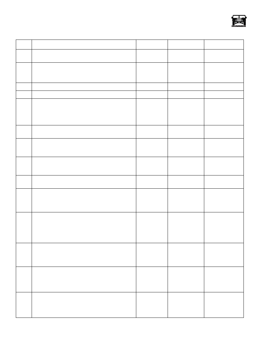
Locate and repair short to ground in the status center
Ignition Feed circuit.
Is the action complete?
—
Go to Step 20
—
15
Replace the PCM.
NOTE: If the PCM is faulty, then PCM must be pro-
grammed. Go to PCM Replacement and Programming
Procedures.
Is the action complete?
—
Go to Step 20
—
16
1. Check the MIL control circuit for a poor connection at
the status center connector.
2. If a problem is found, repair as necessary.
Was a problem found?
—
Go to Step 20
Go to Step 17
17
1. Remove the status center.
2. Inspect the MIL bulb.
Is the bulb OK?
—
Go to Step 19
Go to Step 18
18
Replace the MIL bulb.
Is the action complete?
—
Go to Step 20
—
19
Replace the status center.
Is the action complete?
—
Go to Step 20
—
20
1. Using the Scan Tool, select “DTC,” “Clear Info.”
2. Attempt to start the engine.
Does the engine start and continue to run?
—
Go to Step 21
Go to Step 2
21
1. Allow engine to idle until normal operating tempera-
ture is reached.
2. Select “DTC,” “Failed This Ign.”
Are any DTCs displayed?
—
Go to Applicable
DTC Table
Go to Step 22
22
Using the Scan Tool, select “Capture Info,” “Review
Info.”
Are any DTCs displayed that have not been diagnosed?
—
Go to Applicable
DTC Table
System OK
No Malfunction Indicator Lamp (MIL) “Check Engine”
Step
Action
Value(s)
Yes
No
10
PCM/Tech 1 Scan Tool
_____________________________________________________
®
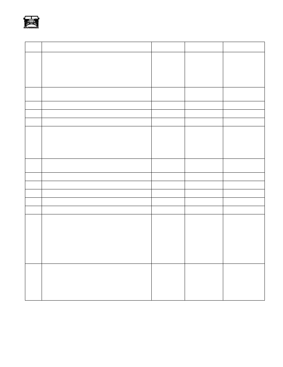
No Scan Tool Data
Step
Action
Value(s)
Yes
No
1
Was the “On-Board Diagnostic (OBD) System Check”
performed?
—
Go to Step 2
Go to OBD System
Check
2
1. Ignition “OFF” for 30 seconds.
2. Ignition “ON,” Engine “OFF.”
Is the MIL “ON”?
—
Go to Step 3
Go to Chart A-1
3
Can the Scan Tool communicate with the PCM?
—
Go to Step 4
Go to Step 7
4
With the Scan Tool, command the MIL “ON” and “OFF.”
—
Go to Step 17
Go to Step 5
5
1. Ignition “OFF.”
2. Disconnect the PCM connectors.
3. Ignition “ON.”
Is the MIL “OFF”?
—
Go to Step 6
Go to Step 18
6
With the Scan Tool, check Engine Cal ID.
Is the proper CAL ID present?
—
Go to Step 28
Go to Step 19
7
With a test light to ground, probe the DLC connector (pin
16).
Is the test light “ON”?
—
Go to Step 8
Go to Step 20
8
With a test light to B+, probe the DLC connector (pins 4
and 5).
Is the test light “ON” for both circuits?
—
Go to Step 9
Go to Step 21
9
Check for proper operation of the cigar lighter.
Does the cigar lighter operate properly?
—
Go to Step 10
Go to Step 22
10
Verify proper operation of the Scan Tool with a known
good vehicle with the same equipment/controller.
Does the Scan Tool communicate with known good vehi-
cle?
—
Go to Step 11
Go to Step 23
11
1. Disconnect the Scan Tool.
2. With the DVM connected to ground, check the PCM
serial data line at the DLC connector (pin 2).
Is voltage on the serial data line less than the specified
value?
7v
Go to Step 12
Go to Step 15
12
With the DVM connected to ground, again check the
PCM serial data line at the DLC connector (pin 2).
Is voltage on the serial data line less than the specified
value?
1v
Go to Step 13
Go to Step 16
13
1. Ignition “OFF.”
2. With the DVM connected to ground, check resistance
of the serial data line at the DLC connector (pin 2).
Is resistance less than the specified value?
10 Ohms
Go to Step 14
Go to Step 27
14
1. Disconnect the PCM connectors.
2. With the DVM connected to ground check resistance
of the serial data line at the DLC connector (pin 2).
Is resistance less than the specified value?
10 Ohms
Go to Step 24
Go to Step 28
_____________________________________________________
PCM/Tech 1 Scan Tool 11
®
05745159
15
1. Ignition “OFF.”
2. Disconnect the PCM Connectors.
3. Ignition “ON.”
4. Check voltage on the DLC connector (pin 2).
Is voltage at the specified value?
0v
Go to Step 28
Go to Step 25
16
Reprogram the EEPROM and retest.
Is serial data present?
—
Go to Step 26
Go to Step 28
17
System OK.
—
—
—
18
Repair short to ground on the MIL control circuit.
—
—
—
19
Reprogram the EEPROM and retest.
—
—
—
20
1. Check fuse number 7.
2. If fuse is blown, repair short to ground in the battery
feed circuit to the DLC connector (pin 16).
3. If the fuse is OK, repair open in the battery feed circuit
to the DLC connector (pin 16).
—
—
—
21
Repair open in circuit that did not light the test light.
Refer to Section 12 for ground distribution.
—
—
—
22
Refer to Section 12 for cigar lighter repair.
—
—
—
23
Faulty Scan Tool and/or cable.
—
—
—
24
Repair short to ground in the serial data line.
—
—
—
25
Repair short to voltage in the serial data line.
—
—
—
26
System OK.
—
—
—
27
1. Check serial data line for an open.
2. If OK, check PCM and DLC connections.
3. If OK, replace the PCM.
NOTE:
If the PCM is faulty, the new PCM must be
programmed. Go to PCM replacement and pro-
gramming procedures.
Is the action complete?
—
Go to OBD
System Check
—
28
Replace the faulty PCM.
NOTE:
if the PCM is faulty, the new PCM must be
programmed. Go the PCM replacement and pro-
gramming procedures.
Is the action complete?
—
Go to OBD
System Check
—
No Scan Tool Data
Step
Action
Value(s)
Yes
No

12
PCM/Tech 1 Scan Tool
_____________________________________________________
®
Engine Cranks But Will Not Start
Step
Action
Value(s)
Yes
No
1
NOTE:
Before clearing DTC(s) use the Scan Tool “Cap-
ture Info” to record Freeze Frame and Failure Record for
reference, as data will be lost when “Clear Info” function
is used.
Was the “On-Board Diagnostic (OBD) System Check”
performed?
—
Go to Step 2
Go to OBD System
Check
2
Check for proper condition of batteries.
Is condition of batteries OK?
—
Go to Step 3
Go to Step 23
3
Check for adequate fuel in tank.
Is fuel at an adequate level?
—
Go to Step 4
Go to Step 23
4
Check the quality of fuel.
Is fuel quality OK?
—
Go to Step 5
Go to Step 23
5
Check glow plug system operation.
Are glow plugs operating OK?
—
Go to Step 6
Go to Step 23
6
Check for proper cranking speed.
Is cranking speed OK?
—
Go to Step 7
Go to Step 23
7
Check for a restriction in the fuel return system.
Does the fuel return system operate properly?
—
Go to Step 8
Go to Step 23
8
Check injection pump ground wire (located on top of the
injection pump).
Is ground OK?
—
Go to Step 9
Go to Step 23
9
Ignition “ON”.
Does MIL come “ON”?
Go to Step 10
Go to “No Malfunc-
tion Indicator
Lamp” on page 8.
10
Install scan tool.
Does scan tool display data?
—
Go to Step 11
Go to “No Scan
Tool Data on
page 10.
11
1. Loosen injector line at injector.
2. Crank engine.
3. Repeat for the remaining injectors.
Is there fuel coming out of injection line?
—
Go to Step 17
Go to Step 12
12
Disconnect Optical/Fuel temperature sensor.
Does vehicle start?
—
Go to Step 16
Go to Step 13
13
1. Reconnect Optical/Fuel temperature sensor.
2. Disconnect fuel solenoid driver.
3. With J–39200 connected to ground, probe fuel inject
control circuit at harness terminal (terminal A).
4. Crank engine.
Is voltage greater than or equal specified value?
1.2v
Go to Step 14
Go to Step 18
14
1. Fuel solenoid driver still disconnected.
2. Jumper closure ground circuit (terminal C) with a test
light connected to B+ at the harness terminal.
Is test light “ON”?
—
Go to Step 15
Go to Step 19
Нет комментариевНе стесняйтесь поделиться с нами вашим ценным мнением.
Текст