Hummer H1 (2002+). Manual — part 270
_____________________________________________________
PCM/Tech 1 Scan Tool 13
®
05745159
15
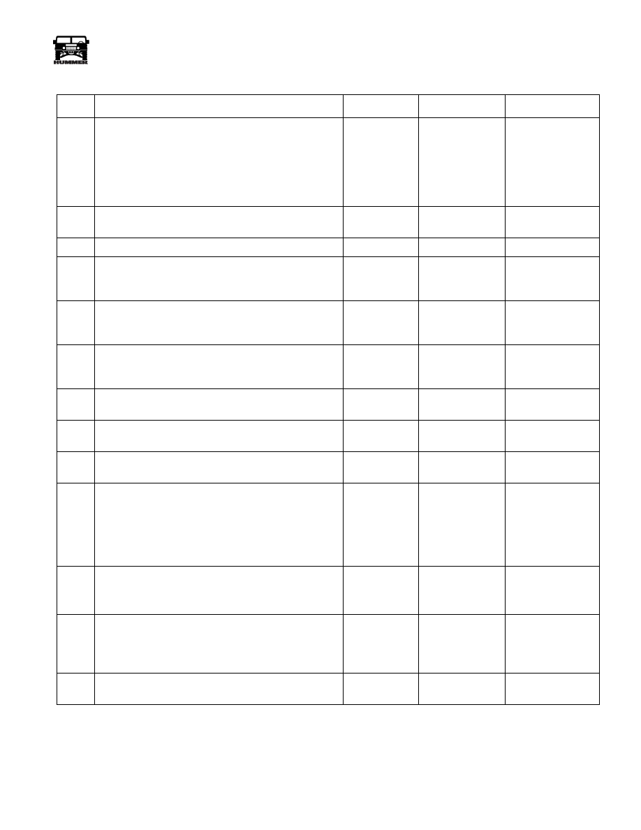
1. Turn the ignition “ON,” engine “OFF.”
2. Verify the fuel solenoid is still disconnected.
3. Probe ignition feed circuit (terminal D) at the fuel sole-
noid harness connector with a test light connected to
ground.
Is test light “ON”?
—
Go to Step 16
Go to Step 21
16
Replace fuel injection pump.
Is the action complete?
—
Go to Step 25
—
17
Injection system OK,
—
—
—
18
Check the fuel inject control circuit for an open or ground
between the fuel solenoid driver and the PCM.
Was a problem found?
—
Go to Step 22
Go to Step 20
19
Check the closure ground circuit for an open between the
fuel solenoid driver and the PCM.
Was a problem found?
—
Go to Step 22
Go to Step 20
20
Inspect the fuel solenoid driver connector and PCM con-
nector for proper connection.
Was a problem found?
—
Go to Step 22
Go to Step 24
21
Repair the open in the ignition feed circuit.
Is action complete?
—
Go to Step 25
—
22
Repair the circuit as necessary.
Is the action complete?
—
Go to Step 25
—
23
Make appropriate repairs.
Is action complete?
—
Go to Step 25
—
24
Replace the faulty PCM.
NOTE:
If the PCM is faulty, the new PCM must be
programmed. Go to PCM replacement and pro-
gramming procedures.
Is the action complete?
—
Go to Step 25
—
25
1. Using the Scan Tool, select “DTC,” “Clear Info.”
2. Attempt to start engine.
Does the engine start and continue to run?
—
Go to Step 26
Go to Step 2
26
1. Allow engine to idle until normal operating tempera-
ture is reached.
2. Select “DCT,” “Fail this Ign.”
Are any DTCs displayed?
—
Go to Step 27
—
27
Using the scan tool, select “Capture Info,” Review Info.”
Are any DTCs displayed that have not been diagnosed?
—
Go to the applica-
ble DTC table
System OK
Engine Cranks But Will Not Start
Step
Action
Value(s)
Yes
No
14
PCM/Tech 1 Scan Tool
_____________________________________________________
®
DTC (DTC) IDENTIFICATION
The MIL (Service Engine Soon) lamp will be “ON” if an emis-
sion malfunction exists. If the malfunction clears, the lamp will
go “OFF” and the DTC will be stored in the PCM. Any DTCs
stored will be cleared if no problem recurs within l50 engine
starts.
• All DTCs with the sign * are transmission related DTCs
and have descriptions, diagnostic charts are in Section 5.
Remember, always start with the lowest numerical en-
gine DTC first. When diagnosing some engine DTCs,
other transmission symptoms can occur.
Intermittents
A corresponding DTC will be stored in the memory of the
PCM as a history DTC until DTCs have been cleared. When
unexpected DTCs appear during the code reading process, one
can assume that these DTCs were set by an intermittent mal-
function and could be helpful in diagnosing the system. An in-
termittent DTC may or may not re-set. If it is an intermittent
failure, a Diagnostic Trouble Code (DTC) chart is not used.
Consult the “Diagnostic Aids” on the page facing the diagnos-
tic chart corresponding to the intermittent DTC. Section “2”
also covers the topic of “Intermittents”. A physical inspection
of the applicable sub-system most often will not resolve the
problem.
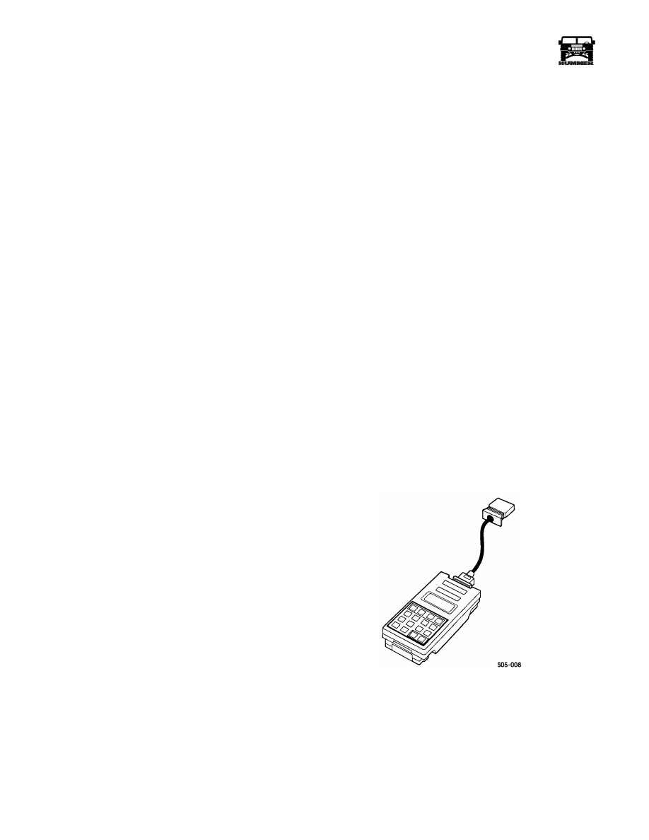
Scan Tool Use With Intermittents
In some scan tool allocations, the data update rate makes the
tool less effective than a voltmeter, such as when trying to de-
tect an intermittent problem which lasts for a very short time.
However, the scan tool allows manipulation of wiring har-
nesses or components under the hood with the engine not run-
ning, while observing the scan tool readout.
The scan tool can be plugged in and observed while driving the
vehicle under the condition when the MIL “Service Engine
Soon” light turns “ON” momentarily or when the engine drive-
ability is momentarily poor. If the problem seems to be related
to certain parameters that can be checked on the scan tool, they
should be checked while driving the vehicle. If there does not
seem to be any correlation between the problem and any spe-
cific circuit, the scan tool can be checked on each position,
watching for a period of time to see if there is any change in the
reading that indicates intermittent operation.
The scan tool is also an easy way to compare the operating pa-
rameters of a poorly operating engine with those of a known
good one. For example, a sensor may shift in value but not set a
DTC. Comparing the sensor’s readings with those of a known
good vehicle may uncover the problem.
The scan tool has the ability to save time in diagnosis and pre-
vent the replacement of good parts. The key to using the scan
tool successfully for diagnosis lies in the technician’s ability to
understand the system he is trying to diagnose as well as under-
standing of the scan tool operation and limitations. The techni-
cian should read the tool manufacturer’s operating manual to
become familiar with the tool’s operation.
_____________________________________________________
PCM/Tech 1 Scan Tool 15
®
05745159
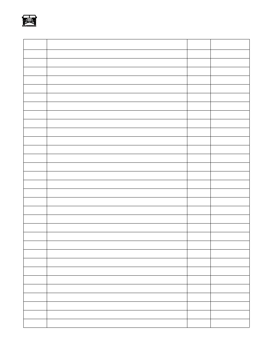
Diagnostic Trouble Code (DTC) Identification
DTC
Description
Type
Illuminate MIL
P0112
IAT Sensor Circuit Low Voltage
B
Yes
P0113
IAT Sensor Circuit High Voltage
B
Yes
P0117
ECT Sensor Circuit Low Voltage
B
Yes
P0118
ECT Sensor Circuit High Voltage
B
Yes
P0121
APP Sensor 1 Circuit Performance
C
No
P0122
APP Sensor 1 Circuit Low Voltage
C
No
P0123
APP Sensor 1 Circuit High Voltage
C
No
P0182
Fuel Temperature Sensor Circuit Low Voltage
B
Yes
P0183
Fuel Temperature Sensor Circuit High Voltage
B
Yes
P0215
Engine Shutoff Control Circuit
D
No
P0216
Injection Timing Control System
B
Yes
P0219
Engine Overspeed Condition
D
No
P0220
APP Sensor 2 Circuit
C
No
P0221
APP Sensor 2 Circuit Performance
C
No
P0222
APP Sensor 2 Circuit Low Voltage
C
No
P0223
APP Sensor 2 Circuit High Voltage
C
No
P0225
APP Sensor 3 Circuit
C
No
P0226
APP Sensor 3 Circuit Performance
C
No
P0227
APP Sensor 3 Circuit Low Voltage
C
No
P0228
APP Sensor 3 Circuit High Voltage
C
No
P0231
Lift Pump Secondary Circuit Low Voltage
B
Yes
P0236
TC Boost System
B
Yes
P0237
TC Boost Sensor Circuit Low Voltage
B
Yes
P0238
TC Boost Sensor Circuit High Voltage
B
Yes
P0251
Injection Pump Cam System
A
Yes
P0263
Cylinder Balance System Fault
D
No
P0266
Cylinder Balance System Fault
D
No
P0269
Cylinder Balance System Fault
D
No
P0272
Cylinder Balance System Fault
D
No
P0275
Cylinder Balance System Fault
D
No
P0278
Cylinder Balance System Fault
D
No
P0281
Cylinder Balance System Fault
D
No

16
PCM/Tech 1 Scan Tool
_____________________________________________________
®
P0284
Cylinder Balance System Fault
D
No
P0335
CKP Sensor Circuit Performance
A
Yes
P0370
Timing Reference High Resolution
A
Yes
P0380
Glow Plug Circuit Performance
B
Yes
P0501
Vehicle Speed Sensor Circuit
D
No
P0567
Cruise Resume Circuit
D
No
P0568
Cruise Set Circuit
D
No
P0571
Cruise Brake Switch Circuit
D
No
P0601
PCM Memory
D
No
P0602
PCM Not Programmed
D
No
P0606
PCM Internal Communication Interrupted
A
Yes
P1125
APP System
C
No
P1214
Injection Pump Timing Offset
B
Yes
P1216
Fuel Solenoid Response Time Too Short
D
No
P1217
Fuel Solenoid Response Time Too Long
D
No
P1218
Injection Pump Calibration Circuit
B
Yes
P1621
EEPROM Write
B
Yes
P1627
A/D Performance
B
Yes
P1635
5 Volt Reference Low
D
No
P1641
Malfunction Indicator Lamp (MIL) Control Circuit
D
No
P1643
Write to Start Lamp Control Circuit
B
No
P1654
Service Throttle Soon (STS) Lamp Control Circuit
D
No
P1656
Wastegate Solenoid Control Circuit
B
Yes
Diagnostic Trouble Code (DTC) Identification (Contd)
DTC
Description
Type
Illuminate MIL
Нет комментариевНе стесняйтесь поделиться с нами вашим ценным мнением.
Текст