Hummer H1 (2002+). Manual — part 89

___________________________________________
Transmission/Transfer Case 5-155
®
05745159
FRONT OUTPUT SHAFT SEAL REPLACEMENT
1.
Mark front propeller shaft and transfer case yoke for align-
ment reference.
2.
Disconnect front propeller shaft at yoke. Retain U-bolts
and nuts (Figure 5-76).
3.
Remove yoke nut (Figure 5-77).
4.
Remove yoke and seal washer. Use tool J–8614-01 to
remove yoke if necessary.
5.
Remove seal from front case bore with standard hook type
seal puller.
6.
Coat outer edge of new seal with thin coat of RTV type
sealer.
7.
Lubricate seal lip with transmission fluid and install seal
with tool J–38869.
CAUTION: The seal can be installed incorrectly. Be sure the
seal lip is toward the case interior.
8.
Smooth seal contact surface of yoke with 320-400 grit
emery coated with transmission fluid. Then clean and
install yoke.
9.
Install yoke seal washer.
10. Install and tighten yoke nut to 90-130 lb-ft (122-176 N•m)
torque.
11. Connect propeller shaft to yoke. Tighten U-bolt nuts to 13-
18 lb-ft (18-24 N•m) torque.
12. Check and top off transfer case fluid level if necessary.
Figure 5-76: Disconnecting/Connecting Front
Propeller Shaft
Figure 5-77: Front Output Shaft Yoke and Seal
Removal/Installation
TRANSFER CASE FLUID CHANGE
The transfer case fill and drain plugs are both located in the
rear case (Figure 5-78).
Correct fill level is to the lower edge of the fill plug hole. Rec-
ommended fluid is Dexron III.
1.
Place vehicle on level surface. Or, if vehicle is raised on
hoist for fluid change, a drive-on hoist is preferred. Vehicle
must be level for accurate refill fluid level.
2.
Remove drain and fill plugs and drain fluid into approved
container.
3.
Install and tighten drain plug to 15-25 lb-ft (20-33 N•m)
torque.
4.
Refill transfer case with Dexron III. Correct level is to
lower edge of fill plug hole.
5.
Install and tighten fill plug to 15-25 lb-ft (20-33 N•m)
torque.
6.
Lower vehicle, if on hoist.
Figure 5-78: Transfer Case Drain and Fill Plug
Locations
U-BOLT
YOKE
FRONT
PROPELLER
SHAFT
YOKE
NUT
SEAL
WASHER
YOKE
OIL SEAL
FILL
PLUG
DRAIN
PLUG

5-156
Transmission/Transfer Case
___________________________________________
®
TRANSFER CASE REMOVAL
1.
Remove drain plug and drain oil from transfer case. Rein-
stall drain plug afterward.
2.
Disconnect propeller shafts from transfer case.
3.
Disconnect wiring harness connectors from vehicle speed
sensors range switch, and lock switch.
4.
Remove wiring harness clamp and move harness away
from transfer case.
5.
Disconnect vent line from transfer case (Figure 5-72).
6.
Disconnect cooler hoses at transfer case (Figure 5-79).
7.
Disconnect shift rod at range lever (Figure 5-80).
8.
Remove guide cable and bracket (Figure 5-80).
Figure 5-79: Cooler Hose Connections
9.
Support transfer case with jack. Secure transfer case to
jack with chain.
10. Remove nuts attaching transfer case to transmission
adapter (Figure 5-81).
Figure 5-80: Shift Rod Attachment
Figure 5-81: Separating Transfer Case From
Transmission
11. Slide transfer case rearward and remove it from under
vehicle (Figure 5-81).
TRANSFER CASE INSTALLATION
1.
Mount transfer case on jack and secure with chain.
2.
Apply bead of Loctite 518 to mounting surface of
transmission adapter.
3.
Align and install transfer case on transmission. Tighten
transfer case attaching nuts to 37 lb-ft (50 N•m).
4.
Remove jack.
5.
Connect shift rod to range lever with washer and cotter pin
(Figure 5-80).
6.
Install guide cable and bracket.
7.
Connect transfer case vent line.
8.
Connect cooler hoses to transfer case cooler fittings.
9.
Connect front and rear propeller shafts to transfer case.
Tighten front shaft U-bolt nuts to 13-18 lb-ft (18-24 N•m)
torque.
10. Install vehicle speed sensor.
11. Install range and lock indicator switches.
12. Attach harness clamp to transfer case.
13. Connect wiring harness connectors to speed sensor and
switches.
14. Fill transfer case to bottom edge of fill plug hole with
Dexron III.
15. Check and adjust shift rod if necessary.
TRANSFER CASE
COOLER
HOSES
RANGE
LEVER
SHIFT ROD
GUIDE
CABLE AND
BRACKET
EXHAUST
BRACKET
FLAT
WASHERS
WAVY
WASHER
TRANSMISSION
ADAPTER
TRANSFER CASE
___________________________________________
Transmission/Transfer Case 5-157
®
05745159
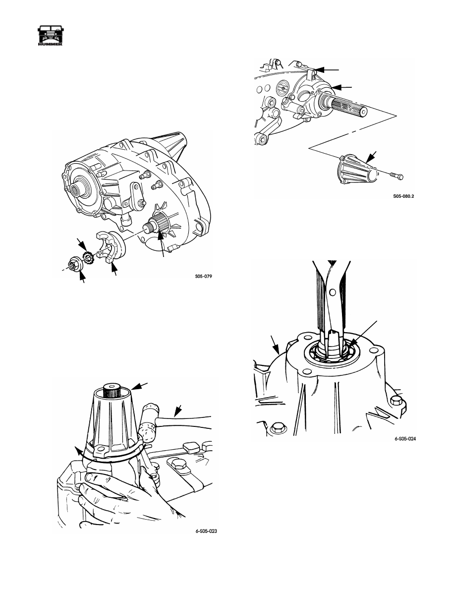
TRANSFER CASE DISASSEMBLY AND
OVERHAUL
1.
Remove vehicle speed sensor and both indicator switches.
2.
Remove front output shaft yoke (Figure 5-82). Remove
yoke nut with suitable size socket and impact wrench.
Then remove seal washer and yoke.
Figure 5-82: Front Yoke Removal/Installation
3.
Remove extension housing bolts. Then tap housing in
counterclockwise direction to break sealer bead
(Figure 5-83). Use plastic mallet to tap housing.
4.
Remove extension housing (Figure 5-84).
Figure 5-83: Loosening Extension Housing
Figure 5-84: Extension Housing Removal
5.
Remove rear retainer bolts. Then remove mainshaft
bearing snap ring (Figure 5-85).
6.
Pry rear retainer upward at each lug with screwdriver
(Figure 5-86). Remove retainer after breaking sealer bead.
Figure 5-85: Mainshaft Snap Ring Bearing Removal
SEAL
WASHER
YOKE
NUT
YOKE
FRONT
OUTPUT
SHAFT
EXTENSION
HOUSING
PLASTIC
MALLET
REAR
CASE
REAR
RETAINER
EXTENSION
HOUSING
REAR
RETAINER
SNAP RING

5-158
Transmission/Transfer Case
___________________________________________
®
Figure 5-86: Rear Retainer Removal
7.
Remove speedometer tone wheel and snap rings
(Figure 5-87).
8.
Remove rear case attaching bolts and remove rear case
(Figure 5-88).
CAUTION: Loosen the rear case with screwdrivers positioned
in the slot at each end of the case. This will avoid damaging the
case sealing surfaces.
Figure 5-87: Speedometer Tone Wheel Removal/In-
stallation
Figure 5-88: Rear Case Removal
9.
Remove oil pump, pickup tube, hose, and screen
(Figure 5-89).
10. Remove O-ring from oil pump inlet port (Figure 5-90).
Figure 5-89: Oil Pump Assembly Removal
LUG
LUG
SCREWDRIVER
REAR
RETAINER
MAINSHAFT
SNAP RING
TONE WHEEL
SNAP RING
REAR
CASE
REAR
CASE
OIL
PUMP
OIL PUMP
OIL PICKUP
TUBE
HOSE
OIL SCREEN
REAR CASE
Нет комментариевНе стесняйтесь поделиться с нами вашим ценным мнением.
Текст