Hummer H1 (2002+). Manual — part 90

___________________________________________
Transmission/Transfer Case 5-159
®
05745159
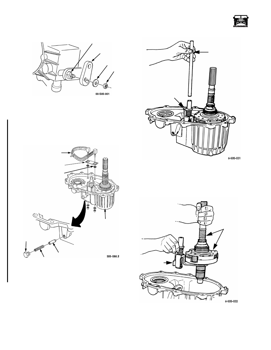
Figure 5-90: Oil Pump O-ring Location
11. Remove drive sprocket snap ring (Figure 5-91).
12. Remove drive sprocket (Figure 5-92).
13. Remove drive chain.
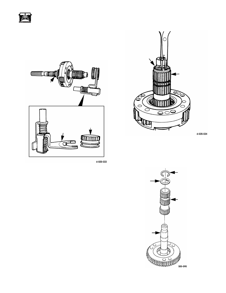
14. Remove front output shaft and driven sprocket as
assembly (Figure 5-93).
Figure 5-91: Drive Sprocket Snap Ring Removal/
Installation
Figure 5-92: Drive Sprocket Removal
Figure 5-93: Front Shaft and Driven Sprocket
Removal
15. Remove range lever nut, washer and lever from sector
shaft (Figure 5-94).
OIL PUMP
INLET PORT
O-RING
DRIVE
SPROCKET
SNAP RING
DRIVE
SPROCKET
DRIVE
SPROCKET
DRIVE
CHAIN
DRIVEN
SPROCKET
FRONT
OUTPUT
SHAFT
5-160
Transmission/Transfer Case
___________________________________________
®
Figure 5-94: Range Lever Mounting
16. Remove detent plug, spring, and plunger (Figure 5-95).
17. Remove oil cooler attaching nuts and washers. Then
remove cooler, support bracket and O-rings (Figure 5-95).
18. Remove shift rail (Figure 5-96).
Figure 5-95: Oil Cooler and Detent Plug, Spring,
Plunger Removal
Figure 5-96: Shift Rail Removal/Installation
19. Remove mainshaft, differential, and mode fork as
assembly (Figure 5-97).
Figure 5-97: Mainshaft, Differential and Mode Fork
Removal
SECTOR SHAFT
RANGE LEVER
WASHER
NUT
OIL COOLER
O-RING
FRONT CASE
PLUNGER
SPRING
DETENT
PLUG
SUPPORT
BRACKET
SHIFT
RAIL
MODE
FORK
ASSEMBLY
MODE FORK
ASSEMBLY
MAINSHAFT AND
DIFFERENTIAL
ASSEMBLY
4-1-00
___________________________________________
Transmission/Transfer Case 5-161
®
05745159
20. Remove mode fork and sleeve from mainshaft
(Figure 5-98). Note position of sleeve for installation
reference. Do not disassemble fork assembly. Only the
fork pads are serviceable.
21. Remove snap ring that secures intermediate clutch shaft
on mainshaft (Figure 5-99).
Figure 5-98: Mode Fork and Sleeve Removal
Figure 5-99: Intermediate Clutch Shaft Snap Ring
Removal/Installation
22. Remove intermediate clutch shaft and tabbed thrust ring
from mainshaft (Figure 5-100).
Figure 5-100: Clutch Shaft Removal
MODE
FORK
ASSEMBLY
MAINSHAFT
MODE
SLEEVE
SNAP RING
INTERMEDIATE
CLUTCH
SHAFT
MAINSHAFT
INTERMEDIATE
CLUTCH SHAFT
THRUST RING
SNAP RING

5-162
Transmission/Transfer Case
___________________________________________
®
23. Remove differential snap ring (Figure 5-101).
24. Remove differential from mainshaft (Figure 5-102).
25. Remove mainshaft needle roller bearings and spacers
(Figure 5-103).
Figure 5-101: Differential Snap Ring Location
Figure 5-102: Differential Removal
Figure 5-103: Mainshaft Bearing and Spacer
Removal
26. Slide low range fork pin out of shift sector. Then remove
low range fork and sleeve as assembly (Figure 5-104).
27. Remove shift sector.
28. Remove shift sector shaft bushing and O-ring
(Figure 5-105).
Figure 5-104: Range Fork and Sleeve Removal
DIFFERENTIAL
SNAP RING
DIFFERENTIAL
MAINSHAFT
MAINSHAFT
NEEDLE
ROLLER
BEARINGS
BEARING
SPACERS
PIN
LOW RANGE
FORK
SLEEVE
SHIFT
SECTOR
Нет комментариевНе стесняйтесь поделиться с нами вашим ценным мнением.
Текст