Hummer H1 (2002+). Manual — part 255
____________________________________________________________
Accessories 13-13
®
05745159
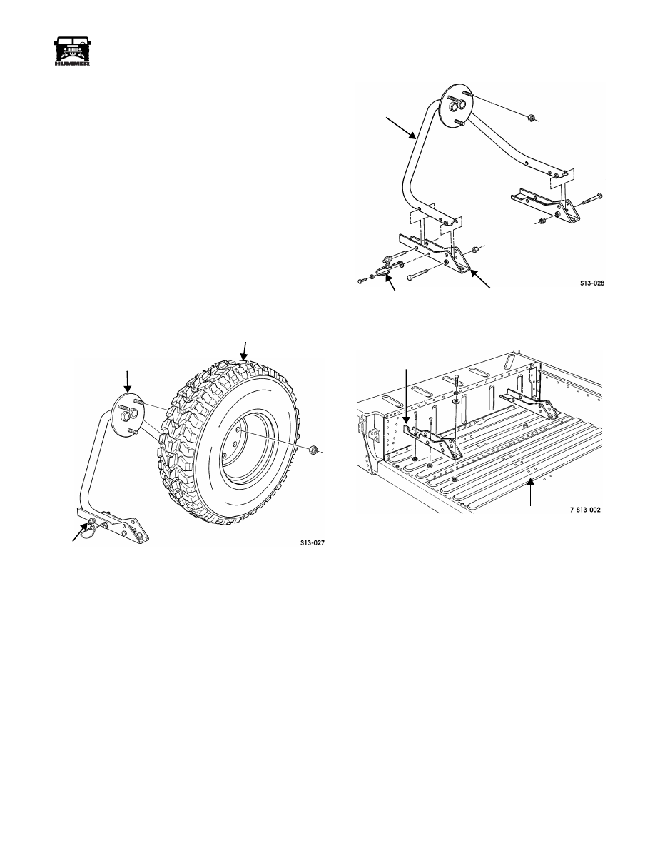
CARGO BED-MOUNTED SPARE TIRE CARRIER
REPLACEMENT
WARNING: Always support the tire and wheel assem-
bly when removing the lug nuts. The tire and wheel as-
sembly weighs approximately 160 lbs (72 kgs) and may
cause personal injury if it is not supported properly.
NOTE: Cargo bed-mounted spare tire carrier may be located
either directly behind the cab or at the left wheelhouse on two
door models. On four door models, spare tire carrier will be lo-
cated at the left wheelhouse.
Removal
NOTE: Perform steps 1 and 2 on vehicles with frame assem-
bly stowed in down position.
1.
Disconnect lock pins and raise frame assembly to upright
position (Figure 13-29).
Figure 13-29: Cargo Bed-Mounted Spare Tire
Carrier Appearance
2.
Secure frame assembly in upright position with lock pins.
3.
Remove lug nuts securing tire to frame assembly and
remove wheel/tire assembly.
4.
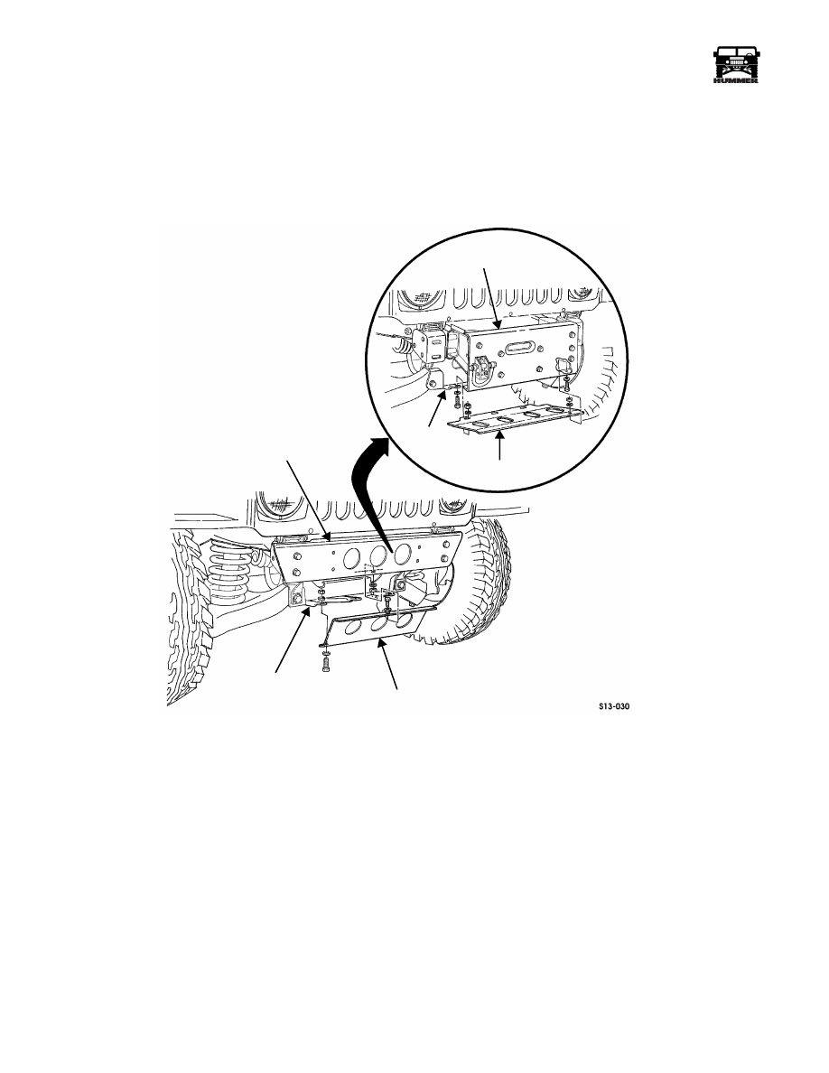
Remove self-tapping screws, lockwashers, and lanyard/lock
pin assemblies from mounting brackets (Figure 13-30).
5.
Remove locknuts, bolts and frame assembly from
mounting brackets.
6.
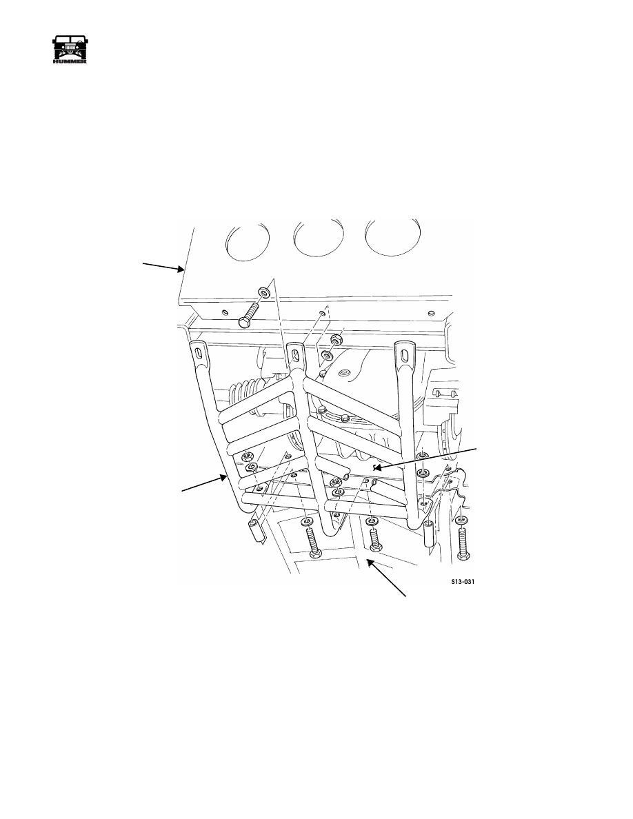
Remove screws securing mounting brackets to cargo floor
(Figure 13-31).
7.
Remove bolts, lockwashers, washers, and mounting
brackets from cargo floor.
Figure 13-30: Frame Assembly Mounting
Figure 13-31: Mounting Bracket Positioning
Installation
1.
Install mounting brackets on cargo floor with washers,
lockwashers, and bolts (Figure 13-31).
2.
Secure mounting brackets to cargo floor with screws.
Tighten screws to 44 lb-ft (60 N•m).
3.
Install frame assembly on mounting brackets with bolts
and locknuts (Figure 13-30).
4.
Install lanyard/lock pin assemblies on mounting brackets
and frame assembly with lockwashers and self-tapping
screws.
5.
With carrier in the upright position, install tire on frame
assembly with three lug nuts (Figure 13-29).
NOTE: Perform steps 6 and 7 to stow frame assembly in down
position.
6.
Disconnect lock pins and lower frame assembly to down
position.
7.
Connect lock pins.
FRAME ASSEMBLY
WHEEL/TIRE ASSEMBLY
LOCK
PIN
LANYARD AND
LOCK PIN ASSEMBLY
MOUNTING
BRACKET
FRAME
ASSEMBLY
MOUNTING
BRACKET
CARGO FLOOR
13-14
Accessories
_____________________________________________________________
®
DRIVELINE PROTECTION
Skid Plate Replacement
Removal
1.
Remove locknuts, washers, bolts, and washers securing
skid plate to front shield (Figure 13-32).
NOTE: Go to step 3 for vehicles equipped with a winch.
2.
Remove locknuts, washers, bolts, washers, and skid plate
from front bumper.
3.
Remove locknuts, washers, bolts, washers, and winch skid
plate from winch bumper.
Figure 13-32: Skid Plate Mounting
Installation
NOTE: Go to step 2 for vehicles equipped with a winch.
1.
Install skid plate on front bumper with bolts, washers, and
locknuts. Tighten locknuts to 24 lb-ft (33 N•m)
(Figure 13-32).
2.
Install winch skid plate on winch bumper with bolts,
washers, and locknuts (Figure 13-32). Tighten locknuts to
24 lb-ft (33 N•m).
3.
Secure skid plate to front shield with bolts, washers, and
locknuts. Tighten locknuts to 24 lb-ft (33 N•m).
WINCH BUMPER
WINCH SKID PLATE
SKID PLATE
FRONT SHIELD
FRONT BUMPER
FRONT
SHIELD
____________________________________________________________
Accessories 13-15
®
05745159
Front Shield Replacement
Removal
1.
Remove locknuts, washers, bolts, and spacers securing
front shield to front crossmember and intermediate shield
(Figure 13-33).
2.
Remove locknuts, washers, bolts, and front shield from
skid plate.
Installation
1.
Install front shield on skid plate with bolts, washers, and
locknuts. Do not tighten locknuts (Figure 13-33).
2.
Secure front shield to front crossmember and intermediate
shield with spacers, bolts, washers, and locknuts.
3.
Tighten locknuts securing front shield to skid plate to 24
lb-ft (33 N•m). Tighten locknuts securing front shield to
crossmember and intermediate shield to 44 lb-ft (60 N•m).
Figure 13-33: Front Shield Mounting
SKID PLATE
FRONT SHIELD
FRONT CROSSMEMBER
INTERMEDIATE SHIELD
13-16
Accessories
_____________________________________________________________
®
Intermediate Shield Replacement
Removal
1.
Remove six locknuts, washers, bolts, washers, and four
rubber washers securing two transmission support brack-
ets and intermediate shield to transmission mount cross-
member. Remove support brackets. Discard locknuts
(Figure 13-34).
Figure 13-34: Intermediate Shield
2.
Remove locknut, washer, capscrew, and washer securing
left support bracket to engine mount bracket and frame
rail. Discard locknut (Figure 13-35).
3.
Remove four locknuts, washers, bolts, washers, and left
support bracket from left mounting bracket. Discard
locknuts.
4.
Remove locknut, washer, capscrew, and washer securing
right support bracket to frame rail. Discard locknut
(Figure 13-36).
5.
Remove four locknuts, washers, bolts, washers, and right
support bracket from right mounting bracket. Discard
locknuts.
6.
Remove two locknuts, washers, bolts, washers, spacers,
and intermediate shield from front crossmember and front
shield. Discard locknuts (Figure 13-37).
Figure 13-35: Left Support Bracket
Figure 13-36: Right Support Bracket
INTERMEDIATE
SHIELD
TRANSMISSION
SUPPORT
BRACKET
RUBBER
WASHERS
TRANSMISSION
MOUNT
CROSSMEMBER
ENGINE
MOUNT
BRACKET
FRAME
RAIL
LEFT SUPPORT
BRACKET
LEFT MOUNTING
BRACKET
FRAME RAIL
RIGHT SUPPORT
BRACKET
RIGHT MOUNTING
BRACKET
Нет комментариевНе стесняйтесь поделиться с нами вашим ценным мнением.
Текст