Hummer H1 (2002+). Manual — part 178
_____________________________________________________________________
Body 10-83
®
05745159
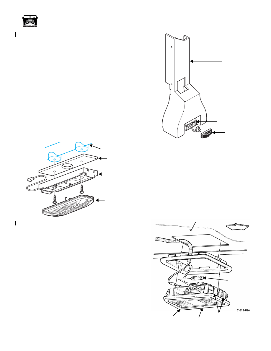
Domelight Replacement (Model 90)
Removal
1.
Using a screwdriver, snap the dome light assembly from
its base (Figure 10-165)
2.
Remove two screws securing domelight base and the
support structure.
3.
Slowly pull the light base until the connector for the roof
harness is exposed.
4.
Disconnect the roof harness from the dome light base.
5.
Remove the dome lamp.
Installation
1.
Connect roof harness to dome light base.
2.
Install two screws through base and support and attach
base to the roof structure.
3.
Install light assembly into base.
4.
Verify operation.
Figure 10-165: Domelight Replacement (Model 90)
Rear Seat Courtesy Light Replacement
Removal
1.
Carefully pry courtesy light from mounting bracket
(Figure 10-166).
2.
Disconnect light from electrical connector.
Installation
1.
Connect courtesy light to the electrical connector
(Figure 10-166).
2.
Snap courtesy light into mounting bracket.
Figure 10-166: Rear Seat Courtesy Light
Replacement
Maplight Replacement
NOTE:
The maplight will illuminate when the optional remote
entry feature is activated.
Removal
Remove maplight assembly from bezel (Figure 10-167).
Installation
Install maplight assembly into bezel.
Figure 10-167: Optional Maplight Replacement
8-S10-005
DOME LIGHT
ASSEMBLY
DOME LIGHT
BASE
SUPPORT
ROOF STRUCTURE
S10-212.3
MOUNTING
COURTESY
BRACKET
LOWER
B-PILLAR
TRIM
LIGHT
HEADLINER
BEZEL
BEZEL
MAPLIGHT
ASSEMBLY
RETAINING
CLIPS
BULB
FRONT OF
VEHICLE
4-1-00
10-84
Body
______________________________________________________________________
®
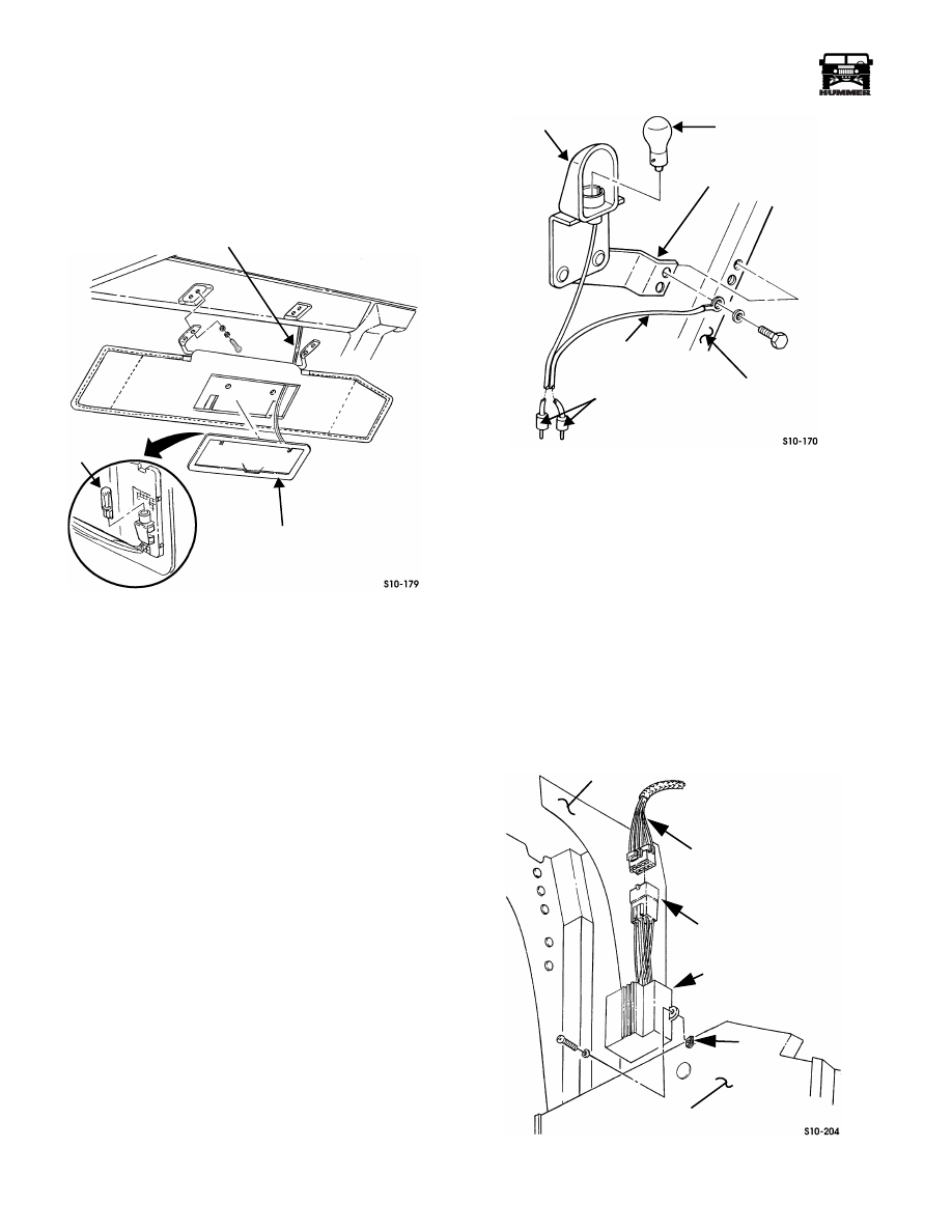
Lighted Visor Mirror Replacement
Removal
1.
Pull mirror assembly from visor (Figure 10-168).
2.
Remove lamp.
Figure 10-168: Lighted Visor Mirror Replacement
Installation
1.
Install lamp (Figure 10-168).
2.
Install mirror assembly by pressing it into the visor.
Underhood Light Replacement
Removal
1.
Disconnect two connectors from wiring harness
(Figure 10-169).
2.
Remove two screws, washers, ground lead, bracket, and
light from hood.
3.
Remove lamp from light.
Installation
1.
Install lamp in light (Figure 10-169).
2.
Secure light, bracket, and ground lead to hood with two
washers and capscrews.
3.
Connect two connectors to wiring harness.
Figure 10-169: Underhood Light Replacement
Daytime Running Lights (DRL) Module
Replacement (Canada Only)
Removal
1.
Disconnect the Daytime Running Lights (DRL) connector
from the harness assembly (Figure 10-170).
2.
Remove two screws, washers, nuts, and DRL module from
the kick panel.
Installation
1.
Secure DRL module to kick panel with two screws, wash-
ers, and nuts (Figure 10-170).
2.
Connect the DRL connector to the harness assembly.
Figure 10-170: Daytime Running LIghts Module
VISOR MIRROR
ASSEMBLY
VISOR MIRROR LEAD
MIRROR ASSEMBLY
REAR VIEW
LAMP
LIGHT
LAMP
BRACKET
HOOD
GROUND LEAD
CONNECTORS
A-PILLAR
DAYTIME RUNNING
LIGHTS CONNECTOR
DAYTIME RUNNING
LIGHTS MODULE
LEFT OUTER
KICK PANEL
HARNESS ASSEMBLY
NUT
SPEED

_____________________________________________________________________
Body 10-85
®
05745159
Front Driver and Passenger Courtesy Light
Replacement
Removal
1.
Carefully pry courtesy light from mounting bracket
(Figures 10-171 and 10-172).
2.
Disconnect light from wiring harness.
Figure 10-171: Front Driver Side Courtesy Light
Replacement
Installation
1.
Connect courtesy light to wiring harness (Figures 10-171
and 10-172).
2.
Snap light into mounting bracket.
Figure 10-172: Front Passenger Side Courtesy Light
Replacement
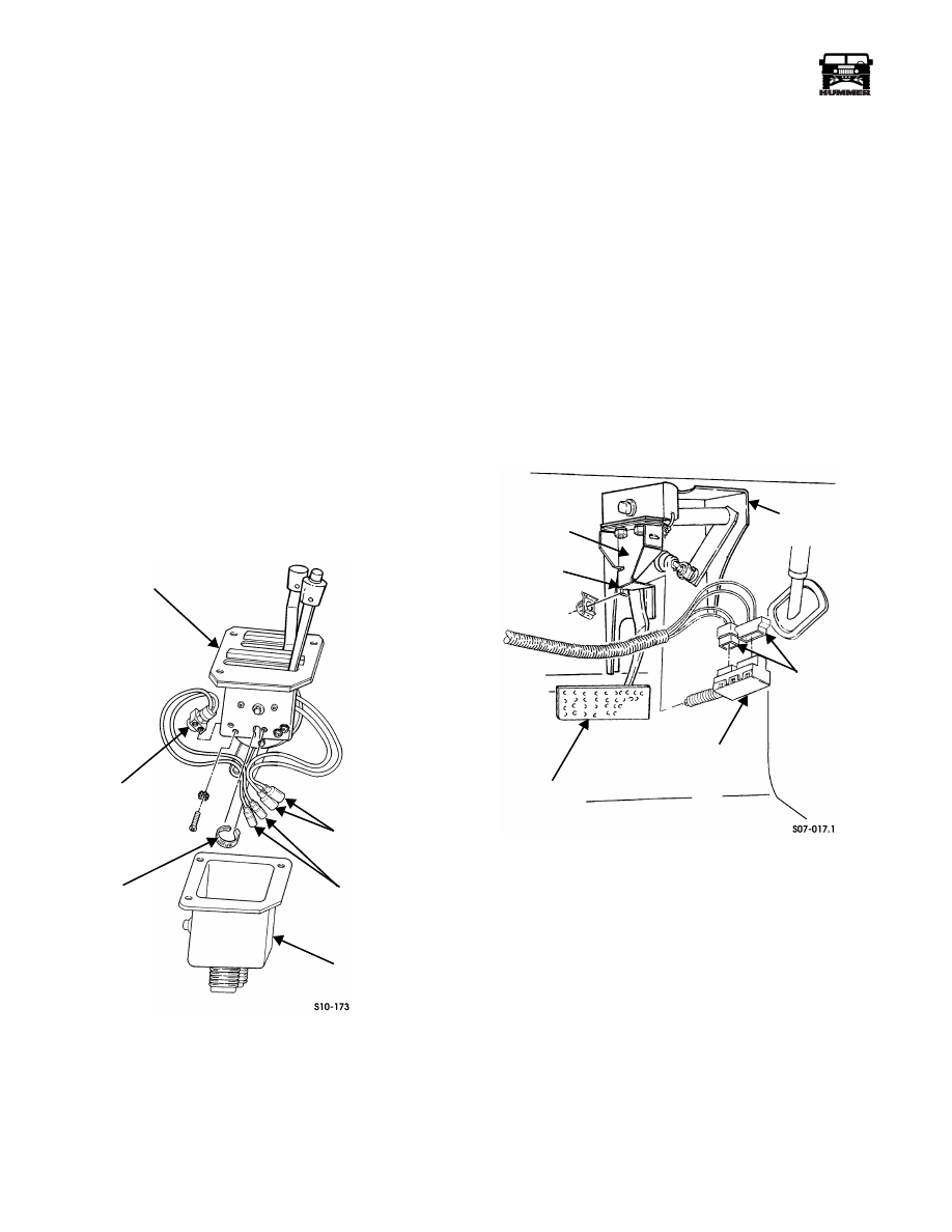
Headlight Electrical Connector and
Grommet Replacement
Removal
1.
Remove headlight and jumper harness.
2.
Remove connector from grommet (Figure 10-173).
3.
Remove grommet from headlight housing.
Installation
1.
Install grommet in headlight housing (Figure 10-173).
2.
Install connector in grommet.
3.
Install jumper harness and headlight.
Figure 10-173: Headlight Electrical Connector
and Grommet Replacement
MOUNTING
WIRING
COURTESY
INSTRUMENT
PANEL
LIGHT
HARNESS
BRACKET
COURTESY LIGHT
MOUNTING BRACKET
CONNECTOR
ELECTRICAL
COURTESY
LIGHT
GROMMET
CONNECTOR
HEADLIGHT
HOUSING
10-86
Body
______________________________________________________________________
®
BACKUP LIGHT SWITCH REPLACEMENT
Removal
1.
Remove shift controls housing (Section 5).
2.
Pull neutral start switch leads, backup light switch leads,
and light lead through boot and remove boot from shift
controls housing (Figure 10-174).
3.
Remove two screws and lockwashers securing backup
light switch to housing.
4.
Remove tiedown strap securing backup light switch to
neutral start switch, and remove backup light switch.
Installation
1.
Secure backup light switch to neutral start switch with
tiedown strap (Figure 10-174).
2.
Secure backup light switch to shift controls housing with
two lockwashers and screws.
3.
Position neutral start switch leads, backup light switch
leads, and light lead through boot, and install boot on
housing.
4.
Install shift controls housing (Section 5).
Figure 10-174: Backup Light Switch Replacement
STOPLIGHT SWITCH REPLACEMENT
Removal
1.
Disconnect two harness leads from stoplight switch
(Figure 10-175).
2.
Remove stoplight switch from bracket.
Installation
1.
Install stoplight switch into bracket (Figure 10-175).
2.
Connect two harness leads to stoplight switch.
Adjustment
1.
Push switch into bracket with brake depressed.
2.
Pull up on brake pedal. Switch should ratchet outward to
proper position.
3.
Check function with engine running.
Figure 10-175: Stoplight Switch Replacement
SHIFT CONTROLS HOUSING
BACKUP LIGHT
TIEDOWN
BOOT
NEUTRAL START
SWITCH LEADS
SWITCH
BACKUP LIGHT
SWITCH LEADS
STRAP
STOPLIGHT
BRAKE PEDAL
SWITCH
HARNESS
BRAKE PEDAL
SWITCH
SUPPORT
ARM
LEADS
ARM
Нет комментариевНе стесняйтесь поделиться с нами вашим ценным мнением.
Текст