Hummer H1 (2002+). Manual — part 177

_____________________________________________________________________
Body 10-79
®
05745159
Side Marker Light Lens and Lamp
Replacement
Removal
Remove two screws, cover, lens, and lamp from lamp holder
(Figure 10-154).
Installation
1.
Install lamp. Secure lens, and cover to lamp holder with
two screws (Figure 10-154).
2.
Ensure side marker light operates properly.
Figure 10-154: Side Marker Light Lens and Lamp
Replacement
Identification Light Replacement
NOTE:
All identification lights are replaced the same. Bulb is
not removable from lens. Light is replaced as an assembly.
Removal
1.
Carefully pry tabbed sides of identification light from light
bracket (Figure 10-155).
2.
Disconnect light from wiring harness.
Installation
1.
Connect identification light to wiring harness
(Figure 10-155).
2.
Snap light into light bracket.
Figure 10-155: Identification Light Replacement
Side Marker Light Assembly Replacement
NOTE:
Replacement of front and rear light assemblies is basi-
cally the same. This procedure covers the front left side
marker.
Removal
1.
Remove four screws, washers, and close-off cover from
hood (Figure 10-156).
2.
Disconnect harness lead from marker light lead
(Figure 10-157).
3.
Remove two screws, cover, and lens from marker light.
4.
Remove four locknuts, washers, ground lead, gasket, four
screws, and marker light from hood.
Figure 10-156: Close-Off Cover Location
LAMP HOLDER
LAMP
LENS
COVER
LIGHT BRACKET
IDENTIFICATION
LIGHT
WIRING HARNESS
TABBED
SIDE
TABBED
SIDE
CLOSE-OFF COVER
HOOD
MARKER
LIGHT
10-80
Body
______________________________________________________________________
®
Figure 10-157: Side Marker Light Assembly
Installation
1.
Secure gasket, lamp holder, and ground lead on hood with
four screws, washers, and locknuts (Figure 10-157).
2.
Secure lens and cover to lamp holder with two screws.
3.
Connect light lead to harness lead.
4.
Secure close-off cover to hood with four washers and
screws (Figure 10-156).
5.
Ensure side marker light operates properly.
Front Turn Signal Light Replacement
Removal
NOTE:
To remove lamp only, perform steps 1 and 2.
1.
Remove four screws, lens, and gasket from turn signal
light (Figure 10-158).
2.
Remove lamp from socket
3.
Remove four screws, washers, and close-off cover from hood.
4.
Disconnect two connectors from wiring harness.
5.
Remove two nut and lockwasher assemblies, washers,
bracket, and light from hood (Figure 10-159).
6.
Remove two screws, lockwashers, and light from bracket.
Figure 10-158: Front Turn Signal Assembly
Breakdown
Figure 10-159: Front Turn Signal Bracket
Installation
NOTE:
To install lamp only, perform steps 5 and 6.
1.
Secure light to bracket with two lockwashers and screws
(Figure 10-159).
2.
Secure bracket and light to hood with two washers and nut
and lockwasher assemblies.
3.
Connect two connectors to wiring harness (Figure 10-158).
4.
Secure close-off cover to hood with four screws and
washers.
5.
Install lamp in socket.
6.
Secure gasket and lens to light with four screws.
7.
Ensure turn signal works properly.
GROUND LEAD
HOOD
DOOR
LENS
MARKER LIGHT
GASKET
HARNESS LEAD
LIGHT LEAD
WIRING
CONNECTORS
CLOSE-OFF
HOOD
LAMP
LIGHT AND
GASKET
LENS
COVER
BRACKET
HARNESS
LIGHT
HOOD
BRACKET

_____________________________________________________________________
Body 10-81
®
05745159
Rear Turn Signal Light Replacement
Removal
NOTE:
To remove lamps only, perform steps 1 and 2.
1.
Remove four screws, lens, and gasket from turn signal
light (Figure 10-160).
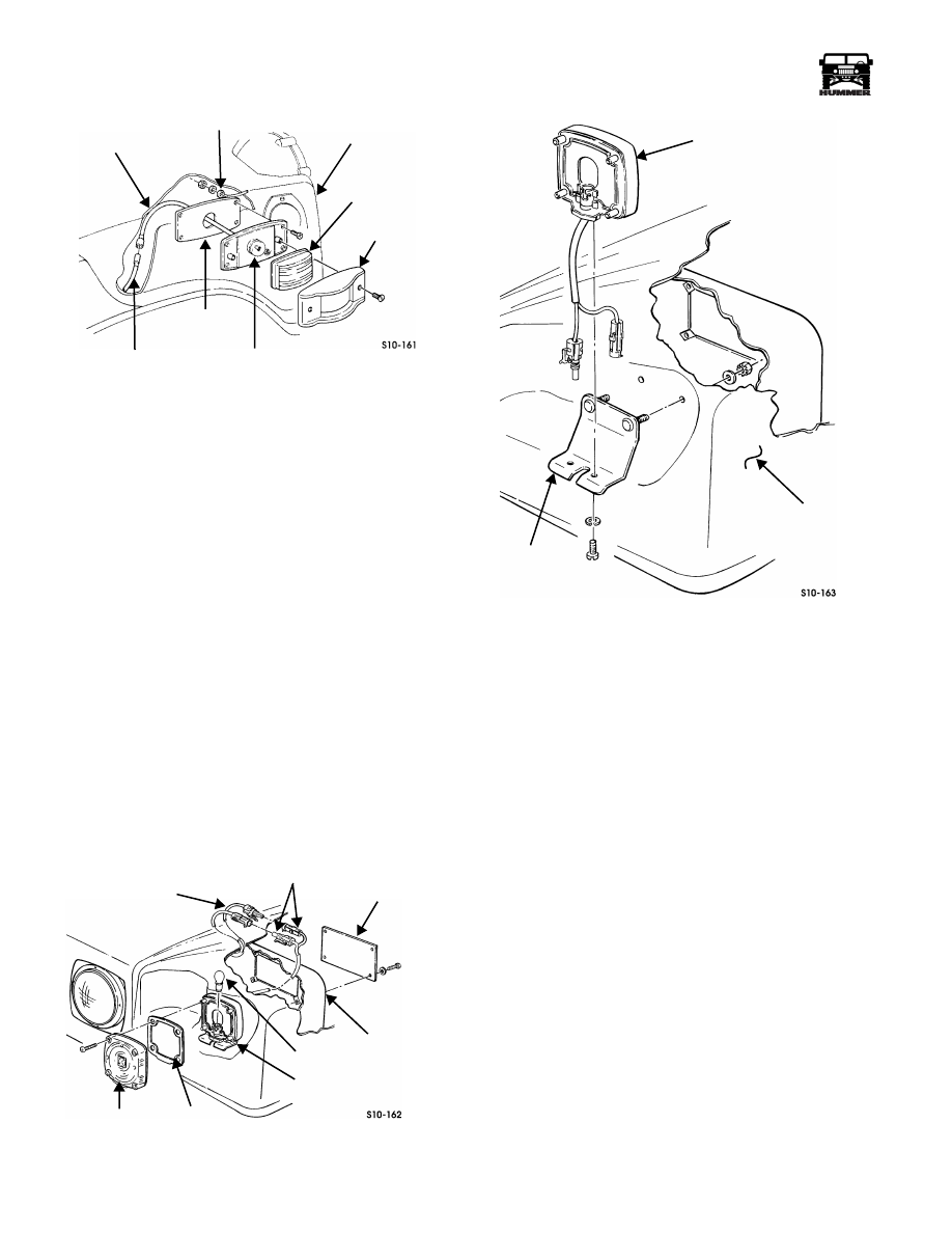
Figure 10-160: Rear Turn Signal Light Assembly
2.
Remove two lamps from sockets.
3.
From behind the light, remove three nuts, lockwashers,
four leads, and three washers securing light to light
housing (Figures 10-160 and 10-161).
4.
Remove two nuts, clamps, and screws securing harness to
shield (Figure 10-161).
5.
Remove two screws, lockwashers, and shield from beam.
6.
Disconnect two connectors from wiring harness.
7.
Remove light and grommet from housing (Figure 10-160).
Installation
NOTE:
To install lamps only, perform steps 6 and 7.
1.
Install light and grommet in housing (Figure 10-160).
2.
Connect two connectors to wiring harness (Figure 10-161).
3.
Secure harness to shield with two screws, clamps, and
nuts.
4.
Secure shield to beam with two lockwashers and screws.
5.
Secure light to light housing with three washers, four leads,
three lockwashers, and nuts (Figures 10-160 and 10-161).
6.
Install two lamps in sockets (Figure 10-160).
7.
Secure gasket and lens to light with four screws.
8.
Ensure turn signal and backup lights work properly.
Figure 10-161: Shield and Wiring Location
Trouble Light Replacement
NOTE:
Parking lights or headlights must be on in order to ac-
tivate the trouble light or the underhood light.
Removal
1.
Disconnect wiring harness from trouble light.
2.
Remove three nut and lockwasher assemblies and trouble
light from mounting bracket.
Installation
1.
Install trouble light on mounting bracket with three nut
and lockwasher assemblies.
2.
Connect wiring harness to trouble light.
HOUSING
GROMMET
LIGHT
LAMPS
GASKET
LENS
SOCKETS
SHIELD
LEADS
HOUSING
WIRING
CONNECTORS
BEAM
HARNESS

10-82
Body
______________________________________________________________________
®
Domelight/Cargo Light Replacement
(Models 83, 84, 89, & 91)
Removal
1.
Remove domelight lens (Figures 10-162 through 10-164).
2.
Remove lamp from domelight.
3.
Remove screws securing domelight to ground lead and
connector.
4.
Remove screw and domelight from roof bracket.
Installation
1.
Secure domelight, connector, and ground lead to roof
bracket with screws (Figures 10-162 through 10-164).
2.
Install lamp in domelight.
3.
Install domelight lens.
Figure 10-162: Standard Domelight Replacement
Figure 10-163: Rear Domelight (HMCS)
Figure 10-164: Cargo Light (HMCS)
ROOF BRACKET
GROUND LEAD
DOMELIGHT
LENS
LAMP
CONNECTOR
FRONT OF
VEHICLE
ROOF BRACKET
GROUND LEAD
DOMELIGHT
LENS
LAMP
CONNECTORS
FRONT OF
VEHICLE
ROOF BRACKET
GROUND LEAD
DOMELIGHT
LENS
LAMP
FRONT OF
VEHICLE
4-1-00
Нет комментариевНе стесняйтесь поделиться с нами вашим ценным мнением.
Текст