Hummer H1 (2002+). Manual — part 296
____________________________________________________
PCM/Tech 1 Scan Tool 117
®
05745159
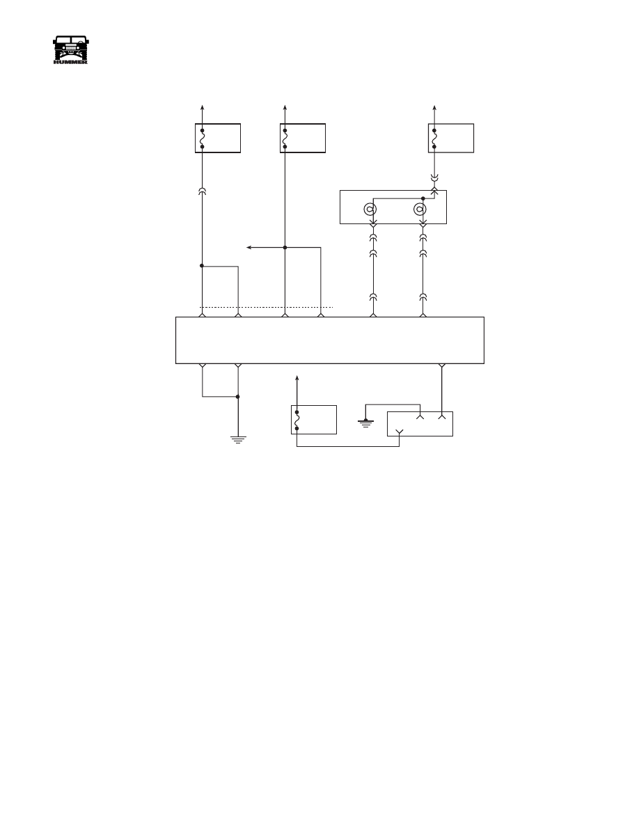
DTC P1654 Check Throttle Circuit
Circuit Description
A dash light is illuminated by the PCM if diagnostics have de-
tected certain errors related to the Accelerator Pedal Position
(APP) sensor. Illumination is accomplished by the PCM pro-
viding a ground path for the light circuit. This is a type D DTC.
Conditions for Setting the DTC
• Check Throttle lamp requested “ON”.
• Voltage at the Check Throttle control circuit is greater
than 0 volts.
or
• Check Throttle lamp requested “OFF”.
• Voltage at the Check Throttle control circuit is equal to
0 volts.
Action Taken When the DTC Sets
Will not turn “ON” the MIL.
Conditions for Clearing the MIL/DTC
• The PCM will turn the MIL off after three consecutive
trips without a fault condition.
• A History DTC will clear when forty consecutive
warm-up cycles that the diagnostic does not fail (coolant
temperature has risen 5°C (40°F) from start up coolant
temperature and engine coolant temperature exceeds
71°C (160°F) that same ignition cycle).
• Use of a scan.
Diagnostic Aids
A faulty bulb or the control circuit shorted to ground will cause
a P1654 to set.
Test Description
Number(s) below refer to the number(s) on the diagnostic ta-
ble.
2. This test checks the ability of the PCM to command the
Check Throttle lamp on during the bulb check (Check
Throttle lamp should be “ON” for 2 seconds and then go
out).
3. This test will check the control circuit for a short to ground.
6. This test will check the control circuit for an open.
FUSE 2D
20 AMP
INTERIOR
STS
LAMP
MIL
LAMP
FUSE 3A
20 AMP
EXTERIOR
HOT AT
ALL TIMES
HOT IN RUN
AND START
HOT IN RUN
AND START
FUSE 4B
5 AMP
INTERIOR
G2
G4
FUSE 1H
5 AMP
INTERIOR
DLC
POWERTRAIN
CONTROL
MODULE
SERIAL DATA
CLASS II
MIL
CONTROL
STS LAMP
CONTROL
914 PP
16
4
2
59 BK
C28-C8
570 BK
C28-D7
C28-D6
GROUND
GROUND
570 BK
BATT
BATT
IGN
IGN
C28-C13
C28-D13
C28-C12
C28-C11
C28-D11
TO
C29-B3
537 OR
239 PK
C1-10
C10-J
C10-H
C10-C
C3-G5
C3-F3
C1-25
C1-28
C28-C14
658 BR
714 RD
STATUS
CENTER
HOT AT
ALL TIMES
9-S12-064
554 GRY
30
GR
Y

118
PCM/Tech 1 Scan Tool
___________________________________________________
®
DTC P1654 - Check Throttle Circuit
Step
Action
Value(s)
Yes
No
1
Important:
Before clearing DTC(s) use the scan tool “Capture Info” to
record freeze frame and failure records for reference, as data will be lost
when “Clear Info” function is used.
Was the “On-Board Diagnostic (OBD) System Check” performed?
—
Go to Step 2.
Go to OBD
System Check.
2
1. Ignition “ON” engine “OFF”.
2. Using a scan tool, command the lamp ON and OFF.
Does the Check Throttle lamp turn ON and OFF with each command?
—
Go to Step 3.
Go to Step 4.
3
DTC is intermittent. If no additional DTCs are stored, refer to “Diagnostic
Aids”. If additional DTCs are stored, refer to those charts(s) first.
Are additional DTCs stored?
—
Go to
applicable
DTC table.
Go to
Diagnostic Aids
4
1. Ignition “OFF”.
2. Disconnect the blue 32 way PCM electrical connector.
3. Ignition “ON” engine “OFF”.
Is the lamp “OFF”?
—
Go to Step 5.
Go to Step 7.
5
With a fused jumper wire connected to ground, probe the lamp control cir-
cuit in the PCM harness connector.
Is the lamp ON?
—
Go to Step 6.
Go to Step 8.
6
1. Check for poor connections at PCM.
2. If a problem was found, repair as necessary.
Was a repair performed?
—
Go to Step 10. Go to Step 9.
7
Check Throttle control circuit is shorted to ground.
Is the action complete?
—
Go to Step 10.
—
8
Check the Check Throttle control circuit for the following:
• opens
• poor connection at PCM
• faulty bulb
• faulty fuse.
Was a problem found?
—
Go to Step 10.
—
9
Replace the faulty PCM. Notice: If the PCM is faulty, the new PCM must
be programmed. Go to PCM replacement and programming procedures.
Is the action complete?
—
Go to Step 10.
—
10
1. Using the Scan Tool, select “DTC”, “Clear Info”.
2. Start engine and idle at normal operating temperature.
3. Select “DTC”, “Specific”, then enter the DTC number which was set.
4. Operate vehicle within the conditions for setting this DTC as specified in
the supporting text.
Does the Scan Tool indicate that this diagnostic Ran and Passed?
—
Go to Step 11.
Go to Step 2.
11
Using the Scan Tool, select “Capture Info”, “Review Info”.
Are any DTCs displayed that have not been diagnosed?
—
Go to the
applicable
DTC table
System OK.

____________________________________________________
PCM/Tech 1 Scan Tool 119
®
05745159
DTC P1656 Wastegate Solenoid Control
Circuit
Circuit Description
The turbocharger wastegate is a vacuum actuated valve used to
control the exhaust gas heat sent to the turbo. The wastegate
pulse width modulated solenoid meters the vacuum level at the
wastegate valve actuator as commanded by the PCM. When
the PCM is commanding the Wastegate solenoid ON, the volt-
age potential of the circuit will be low (near 0 volts). When the
PCM is commanding the wastegate solenoid OFF, the voltage
potential of the circuit will be high (near battery volts). The
primary function of the PCM in this circuit is to supply the
ground for the wastegate solenoid. This is a type B code.
Conditions for Setting the DTC
• Conditions for Setting the DTC
• PCM requested Wastegate solenoid ON.
• Voltage on Wastegate solenoid control circuit high
(near battery volts).
• 2 consecutive faults detected.
• Conditions met for 2 seconds.
• or
• PCM requested Wastegate solenoid OFF.
• Voltage on Wastegate solenoid control circuit low (near
0 volts).
• 2 consecutive faults detected.
• Conditions met for 2 seconds.
Action Taken When the DTC Sets
Low Power.
Conditions for Clearing the MIL/DTC
• The PCM will turn the MIL off after three consecutive
trips without a fault condition.
• A History DTC will clear when forty consecutive
warm-up cycles that the diagnostic does not fail (coolant
temperature has risen 5° C (40° F) from start up coolant
temperature and engine coolant temperature exceeds
71° C (160° F) that same ignition cycle.
• Use of a Scan Tool.
Diagnostic Aids
This diagnostic will set when control circuit does not follow
the PCM command (when the solenoid is requested ON volt-
age will drop, when the solenoid is OFF ignition voltage will
be present). The scan tool has a 5 second ON time abort. The
wastegate solenoid can be commanded ON for as many times
as needed, in 5 second intervals. Its possible DTC P0236 may
set along with DTC P1656. This diagnostic can be checked
during key up. The engine will not respond to scan tool com-
mands at idle (engine unable to achieve boost pressures greater
than BARO at idle) or at any engine speed greater than idle
(PCM control abort to prevent engine damage).
FUSE 5C
10AMP
INTERIOR
FUSE 3A
10 AMP
EXTERIOR
ON/
OFF
SET
COAST
RESUME
ACCEL
HOT IN RUN
AND START
HOT IN RUN
AND START
A
29
42
37
C1
C29-A11
C29-B11
C27-D10
C28-D14
C28-C2
C27-D12
C27-D3
C27-D4
C27-D6
C29-B2
C29-B1
C27-C5
C29-A12
C5-D3
C5-A4
A
B
154 TN
151 GY
152 DB
153 LG
ON / OFF
SIGNAL
SET
COAST
SIGNAL
RESUME
ACCEL
SIGNAL
WASTEGATE
SOLENOID
CONTROL
5 VOLT
REFERENCE
APP 3
SIGNAL
GROUND
APP 1
SIGNAL
GROUND
GROUND
D
B
C
A
G
E
F
J
K
3
1
2
C1
22
20
14
15
60
32
53
17
44
720 TN
717 WH
723 YL
724 DG
725 GY
718 DB
719 BR
721 LB
722 PP
ACCELERATIOR
PEDAL POSITION
SENSOR
POWERTRAIN
CONTROL
MODULE
(PCM)
APP 2
SIGNAL
9-S12-055
B
C
D
295 BR
YL
GRN
RD
120
PCM/Tech 1 Scan Tool
___________________________________________________
®
Test Description
Number(s) below refer to the step number(s) on the Diagnostic
Table.
2. Be sure that both the ON and OFF states are commanded.
Repeat the commands as many times as necessary.
3. This check can detect a partially shorted coil which would
cause excessive current flow. Leaving the circuit energized
for 2 minutes allows the coil to warm up. When warm, the
coil may open (Amps drop to zero), or short (Amp draw
greater than 0.75A).
14.If no trouble is found in the control circuit or the connection
at the PCM, the PCM may be malfunctioning. However, this
is an extremely unlikely failure.
Нет комментариевНе стесняйтесь поделиться с нами вашим ценным мнением.
Текст