Hummer H1 (2002+). Manual — part 295

____________________________________________________
PCM/Tech 1 Scan Tool 113
®
05745159
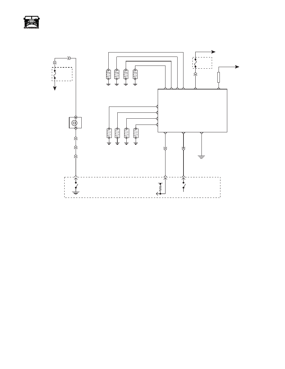
DTC P1641 Malfunction Indicator Lamp
(MIL) Control Circuit
Circuit Description
A dash light is illuminated by the PCM if diagnostics have de-
tected certain errors related to the engine performance or en-
gine sensor status. Illumination is accomplished by the PCM
providing a ground path for the lamp circuit. This is a type D
DTC.
Conditions for Setting the DTC
• MIL requested “ON”.
• Voltage at the MIL control circuit is greater than 0 volts.
or
• MIL requested “OFF”.
• Voltage at the MIL control circuit is greater than 0 volts.
Action Taken When the DTC Sets
Will not turn “ON” the MIL.
Conditions for Clearing the MIL/DTC
• A History DTC will clear when forty consecutive
warm-up cycles that the diagnostic does not fail (coolant
temperature has risen 5°C (40°F) from start up coolant
temperature and engine coolant temperature exceeds
71°C (160°F) that same ignition cycle).
• Use of a scan.
Diagnostic Aids
A faulty bulb or the control circuit shorted to ground will cause
a P1641 to set.
Test Description
Number(s) below refer to the number(s) on the diagnostic ta-
ble.
3. This test will check the control circuit for a short to ground.
5. This test will check the control circuit for an open.
FUSE 2D
20 AMP
INTERIOR
STS
LAMP
MIL
LAMP
FUSE 3A
20 AMP
EXTERIOR
HOT AT
ALL TIMES
HOT IN RUN
AND START
HOT IN RUN
AND START
FUSE 4B
5 AMP
INTERIOR
G2
G4
FUSE 1H
5 AMP
INTERIOR
DLC
POWERTRAIN
CONTROL
MODULE
SERIAL DATA
CLASS II
MIL
CONTROL
STS LAMP
CONTROL
914 PP
16
4
2
59 BK
C28-C8
570 BK
C28-D7
C28-D6
GROUND
GROUND
570 BK
BATT
BATT
IGN
IGN
C28-C13
C28-D13
C28-C12
C28-C11
C28-D11
TO
C29-B3
537 OR
239 PK
C1-10
C10-J
C10-H
C10-C
C3-G5
C3-F3
C1-25
C1-28
C28-C14
658 BR
714 RD
STATUS
CENTER
HOT AT
ALL TIMES
9-S12-064
554 GRY
30
GR
Y

114
PCM/Tech 1 Scan Tool
___________________________________________________
®
DTC P1641 - Malfunction Indicator Lamp (MIL) Control Circuit
Step
Action
Value(s)
Yes
No
1
Important:
Before clearing DTC(s) use the scan tool “Capture Info” to
record freeze frame and failure records for reference, as data will be lost
when “Clear Info” function is used.
Was the “On-Board Diagnostic (OBD) System Check” performed?
—
Go to Step 2.
Go to OBD
System Check.
2
1. Scan tool connected.
2. Ignition “ON” engine “OFF”.
Is the MIL “OFF”?
—
Go to Step 3.
Go to Step 5.
3
1. Ignition “OFF”.
2. Disconnect the blue 32 way PCM electrical connector.
3. Ignition “ON” engine “OFF”.
Is the MIL “ON”?
—
Go to Step 4.
Go to Step 6.
4
MIL control circuit is shorted to ground.
Is the action complete?
—
Go to Step 7.
—
5
1. Check the MIL control circuit for the following:
• opens
• poor connection at PCM
• faulty bulb
• faulty fuse.
Was a problem found?
—
Go to Step 7.
Go to Step 6.
6
Replace the faulty PCM. Notice: If the PCM is faulty, the new PCM must
be programmed. Go to PCM replacement and programming procedures.
Is the action complete?
—
Go to Step 7.
—
7
1. Using the Scan Tool, select “DTC”, “Clear Info”.
2. Start engine and idle at normal operating temperature.
3. Select “DTC”, “Specific”, then enter the DTC number which was set.
4. Operate vehicle within the conditions for setting this DTC as specified in
the supporting text.
Does the Scan Tool indicate that this diagnostic Ran and Passed?
—
Go to Step 8.
Go to Step 2.
8
Using the Scan Tool, select “Capture Info”, “Review Info”.
Are any DTCs displayed that have not been diagnosed?
—
Go to the
applicable
DTC table
System OK.
____________________________________________________
PCM/Tech 1 Scan Tool 115
®
05745159
DTC P1643 Wait to Start Lamp Control Circuit
Circuit Description
A dash light (Wait To Start) is illuminated by the PCM when
the glow plugs are commanded ON. When the PCM is com-
manding the Wait To Start lamp ON, the voltage potential of
the circuit will be low (near 0 volts). When the PCM is com-
manding the Wait To Start lamp OFF, the voltage potential of
the circuit will be high (near battery volts). The primary func-
tion of the PCM is to supply the ground for the Wait To Start
lamp circuit. This is a type B DTC.
Conditions for Setting the DTC
• Wait To Start lamp requested ON.
• Voltage on Wait To Start tamp circuit high (near battery
volts).
or
• Wait To Start lamp requested OFF.
• Voltage on Wait To Start lamp control circuit low (near
0 volts).Action Taken When the DTC Sets
Action Taken When the DTC Sets
No Wait To Start lamp.
Conditions for Clearing the MIL/DTC
• The PCM will turn the MIL off after three consecutive
trips without a fault condition.
• A History DTC will clear when forty consecutive
warm-up cycles that the diagnostic does not fail (coolant
temperature has risen 5° C (40° F) from start up coolant
temperature and engine coolant temperature exceeds
71° C (160° F) that same ignition cycle.
• Use of a Scan tool.
Diagnostic Aids
A faulty bulb or the control circuit shorted to ground will cause
a P1643 to set.
Test Description
5. Repeat the command as many times as necessary (when
glow plugs are commanded ON by the scan tool, an internal
PCM timer protects the glow plugs from damage by cycling
them ON for 3 seconds and OFF for 12 seconds. After the
12 seconds has elapsed, the glow plugs can be commanded
ON again).
9. If no trouble is found in the control circuit or the connection
at the PCM, the PCM maybe malfunctioning, however, this
is an extremely unlikely failure.
FUSE 3A
20 AMP
EXTERIOR
HOT IN RUN
AND START
GLOW PLUG
RELAY
IGN
POWER
FUSIBLE
LINK
W
AIT
WAIT TO START
LAMP CONTROL
C9-J
C9-A
C3-D1
C1-27
C28-C7
GLOW PLUGS RH
GLOW PLUG
RELAY
CONTROL
GLOWPLUG
FEEDBACK
SIGNAL
POWERTRAIN
CONTROL
MODULE
(PCM)
C27-D7
C27-C6
30 GY
466 YL
G1
#1
#3
#5
#7
BK
C5-A4
338 DB
C3-N7
RIGHT
BANK
OUTPUT
00-S12-011
B+
C5-C11
C5-B4
GLOW PLUGS LH
#2
#4
#6
#8
BATT +
LEFT
BANK
OUTPUT
RH STATUS
CENTER
5V
506 LB
239 PK
A
C
TO
STARTER
POS. STUD
B
B
C
D
A
D
C
B
A
D
FUSE 4B
5 AMP
INTERIOR
FUSE BOX
TO
IGNITION
SWITCH

116
PCM/Tech 1 Scan Tool
___________________________________________________
®
DTC P1643 Wait to Start Lamp Control Circuit
Step
Action
Value(s)
Yes
No
1
Important:
Before clearing DTC(s) use the scan tool “Capture Info” to
record freeze frame and failure records for reference, as data will be lost
when “Clear Info” function is used.
Was the “On-Board Diagnostic (OBD) System Check” performed?
Go to step 2
Go to Power-
train OBD
System
Checke
2
1. Turn the ignition ON leaving the engine OFF.
2. Using a scan tool, command the Glow Plug system ON.
Does the lamp turn ON?
Go to step 3
Go to step 4
3
The DTC is intermittent. If no additional DTCs are stored, refer to Diag-
nostic Aids. If additional DTCs were stored refer to those tables(s)
Are additional DTCs stored?
Go to the
applicable
DTC table
Go to Diag-
nostic Aids
4
1. Turn the ignition OFF.
2. Disconnect the PCM connector containing the Wait To Start lamp con-
trol circuit.
3. Turn the ignition ON leaving the engine OFF.
Is the lamp OFF?
Go to step 5
Go to step 7
5
With a fused jumper wire connected to ground, probe the Wait to Start
lamp control circuit in the PCM harness connector.
Is the lamp ON?
Go to step 6
Go to step 8
6
Check the connections at the PCM.
Was a repair performed?
Go to step 10
7
The Wait To Start lamp control circuit is shorted to ground, repair as nec-
essary.
Is the action complete?
Go to step 10
8
Check the Wait To Start circuit for the following:
• Open ignition feed to the bulb
• malfunctioning bulb
• Control circuit open or shorted to B+
Was a repair performed?
Go to step 10
9
Replace the PCM.
Is the action complete?
Go to step 10
10
1. Using the Scan Tool, select “DTC”, “Clear Info”.
2. Start engine and idle at normal operating temperature.
3. Select “DTC”, “Specific”, then enter the DTC number which was set.
4. Operate vehicle within the conditions for setting this DTC as specified
in the supporting text.
Does the Scan Tool indicate that this diagnostic Ran and Passed?
Go to step 11
Go to step 2
11
Does the Scan tool display any additional undiagnosed DTCs?
Go to the
Applicable
DTC table
System OK
Нет комментариевНе стесняйтесь поделиться с нами вашим ценным мнением.
Текст