Hummer H1 (2002+). Manual — part 297

____________________________________________________
PCM/Tech 1 Scan Tool 121
®
05745159
.
DTC P1656 Wastegate Solenoid Control Circuit
Step
Action
Value(s)
Yes
No
1
Important
: Before clearing DTCs use the scan tool Capture Info
Was the Powertrain On-Board Diagnostic (OBD) System Check perfom-
med?
—
Go to Step 2.
Go to OBD
System Check.
2
1. Scan tool connected.
2. Ignition ON, engine OFF.
3. With scan tool, command Boost solenoid ON and OFF and listen for an
audible click.
Does the solenoid turn ON and OFF (audible click) with each command?
—
Go to Step 3.
Go to Step 5.
3
1. Ignition OFF.
2. Disconnect the PCM connector containing the Boost solenoid control
circuit.
3. Ignition ON.
4. Using DVM J–39200 on 10 Amp scale, measure current from the sole-
noid control circuit in the PCM harness connector to ground for 2 min-
utes.
Is current draw less then the specified value, but not zero?.
0.75A
Go to Step 8.
Go to Step 4.
4
1. Ignition OFF.
2. PCM connector still disconnected.
3. Disconnect Boost solenoid.
4. Using DVM J–39200, measure resistance from the solenoid control cir-
cuit in the PCM harness connector to ground.
Does DVM display infinite resistance?
—
Go to Step
13.
Go to Step 10.
5
1. Disconnect Boost solenoid.
2. Ignition ON, engine OFF.
3. Connect a test light between the terminals at the harness connector.
4. Using a scan tool. command the solenoid ON and OFF.
Does test light turn ON and OFF with each command?
—
Go to Step 9.
Go to Step 6.
6
1. Ignition ON engine OFF.
2. With a test light connected to ground, probe the ignition feed circuit at
the Boost solenoid harness connector.
Is the test light ON?
—
Go to Step 7.
Go to Step 12.
7
1. Ignition OFF.
2. Reconnect solenoid.
3. Disconnect the PCM harness containing the solenoid control circuit.
4. Ignition ON.
5. With a fused jumper wire connected to ground, probe the solenoid con-
trol circuit in the PCM hamess connector.
Does the solenoid operate (audible click)?
—
Go to Step
11.
Go to Step 10
8
DTC is intermittent. If no additional DTCs are stored, refer to Diagnostic
Aids. If additional DTCs were stored refer to the applicable DTC table(s)
first.
Are any additional DTCs stored?
—
Go to the
applicable
DTC table
Go to Diag-
nostic Aids
122
PCM/Tech 1 Scan Tool
___________________________________________________
®
9
Check for a poor connection at the Boost solenoid and replace temminals
as necessary.
Did the terminals require replacement?
—
Go to Step
15.
Go to Step 13
10
Repair Boost solenoid control circuit.
Is the action complete?
—
Go to Step
15.
—
11
Check for a poor connection at the PCM, Boost solenoid control circuit.
Was a problem found?
—
Go to Step
15.
Go to Step 14
12
Repair the open in the ignition feed circuit.
Is the action complete?
—
Go to Step
15.
—
13
Replace the Boost solenoid. Refer to Wastegate Solenoid
Is the action complete?
—
Go to Step
15.
—
14
Replace the PCM.
Important
: The new PCM must be programmed.
Refer to PCM Replacement/Programming.
Is the action complete?
—
Go to Step
15.
—
15
1. Using the scan tool, select DTC, Clear Info.
2. Start engine and idle at nommal operating temperature.
3. Select DTC, Specific, then enter the DTC number which was set.
4. Operate vehicle until the Scan Tool indicates that the diagnostic Ran.
Does the scan tool indicate that this diagnostic Passed?
—
Go to Step
15.
Go to Step 2
16
Using the scan tool, select Capture Info, Review Info.
Are any DTCs displayed that have not been diagnosed?
—
Go to the
applicable
DTC table
System OK
DTC P1656 Wastegate Solenoid Control Circuit
Step
Action
Value(s)
Yes
No
____________________________________________________
PCM/Tech 1 Scan Tool 123
®
05745159
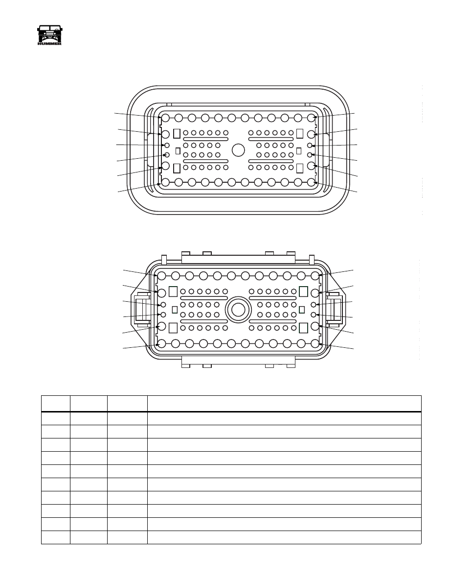
CONNECTOR LEGEND
76 WAY BULKHEAD
LOCATION: LEFT SIDE FIREWALL
PIN
CKT
COLOR
DESCRIPTION
1
400
LG
Ignition Feed +
2
739
PP
Left heated windshield power +
3
740
YL
Right heated windshield power +
4
43
DB
Trailer Brake activation
5
962
BR
Trailer lights
6
33
WH
neutral safety switch feed
7
37E
YL
start relay feed
8
37D
YL
Ignition switch feed
9
786
RD
Fuel selector valve control
10
537
OR
Battery
C1 MALE
9-S12-048
PIN 1
PIN 12
PIN 13
PIN 26
PIN 27
PIN 38
PIN 50
PIN 64
PIN 76
PIN39
PIN 51
PIN 65
C1 FEMALE
9-S12-047
CAV 1
CAV 13
CAV 27
CAV 39
CAV 51
CAV 65
CAV 12
CAV 26
CAV 38
CAV 50
CAV 64
CAV 76

124
PCM/Tech 1 Scan Tool
___________________________________________________
®
11
787
GY
Fuel pump + to selector valve
12
37
RD
Ignition relay feed
13
688
RD
Rear window defrost feed
14
723
YL
APP 3 5volt reference
15
724
DG
APP 3 signal
16
17
PP
+ From dimmer module
17
718
DB
APP 1 signal
18
353
YL
Speedometer signal
19
607
TN
ABS module diagnostic line
20
717
WH
APP 1 5volt reference
21
961
PP
TT4 lamp activation
22
720
TN
APP 2 5volt reference
23
640
OR
IGN+ CTIS warning circuits
24
92
GY
CTIS rear inflate solenoid activation
25
714
DB
Check throttle lamp activation
26
37
RD
Battery feed to interior accessories
27
338
DB
Wait lamp activation
28
658
BR
Check engine lamp activation
29
151
GY
Cruise control ON/OFF signal
30
31
TN
Oil pressure signal
31
22
RD
Brake switch signal – rest
32
721
LB
APP 2 sensor signal
33
580
BR
Not Used for 99
34
606
OR
ABS diagnostic line
35
29
PK
Fuel gauge signal
36
39
DG
Engine temperature signal
37
153
LG
Cruise resume/accelerate signal
38
42
BR
Low brake fluid lamp activation
39
198
TN
A/C request
40
810
PP
TCC brake switch signal
41
2
LG
Right front turn signal
42
152
DB
Cruise set/coast signal
43
298
BR
Backup light switch feed
44
722
PP
APP 2 ground
45
327
YL
Water-in-fuel lamp activation
46
80
WH
Underhood lamp power
PIN
CKT
COLOR
DESCRIPTION
Нет комментариевНе стесняйтесь поделиться с нами вашим ценным мнением.
Текст