Hummer H1 (2002+). Manual — part 278

_____________________________________________________
PCM/Tech 1 Scan Tool 45
®
05745159
DTC P0216 Injection Timing Control System
Circuit Description
Timing of the combustion event is accomplished by delivering
a pulse of fuel into the combustion chamber at a desired degree
of cylinder travel. This desired degree (defines the current po-
sition of the cylinder in relationship of Top Dead Center). This
test compares desired timing to measured timing when certain
conditions have been met. To retard injection timing the PCM
extends the stepper motor. To advance injection timing the
PCM retracts the stepper motor. This is a type B DTC.
Conditions for Setting the DTC
• Engine speed has not changed more than 56 rpm for
20.8 seconds.
• A 5 degree difference between Act. Inj. Time and Des.
Inj. Time.
Action Taken When the DTC Sets
Possible combustion noise.
Conditions for Clearing the MIL/DTC
• The PCM will turn the MIL off after three consecutive
trips without a fault condition.
• A History DTC will clear when forty consecutive
warm-up cycles that the diagnostic does not fail (coolant
temperature has risen 5°C (40°F) from start up
coolant temperature and engine coolant temperature ex-
ceeds 71°C (160°F) that same ignition cycle).
• Use of a Scan Tool.
Diagnostic Aids
A hard start and possible poor performance condition might
exist. Act. Inj. Time will freeze at the point of the fault. DTC
P0216 will set if injection timing is not set correctly. Refer to
Checking and Adjusting Injection Timing.
Test Description
Number(s) refer to the number(s) on the diagnostic table.
2. This step determines is a hard failure or an intermittent.
3. This step checks for an open or short in the injection timing
coil circuit 1.
4. This step checks for an open or short in the injection timing
coil circuit 2.
5. The important thing in this step is that the PCM is sending a
varying voltage (voltage may vary between 1 and 12 (usu-
ally you will see voltage vary between 5 and 6 when engine
is idling)), this will indicate that the PCM is OK and that
there is a problem with the injection timing stepper motor. If
there is a steady voltage present on any circuit, this will indi-
cate a problem with the PCM or a circuit shorted to voltage.
A
E
B
F
D
C
5 VOLT
REFERENCE
OPTICAL/ FUEL
TEMP SENSOR
PUMP CAM
SENSOR
SIGNAL
HIGH
RESOLUTION
SIGNAL
SENSOR
GROUND
M
D
A
B
C
C5
C3
B8
C1
C12
C2
375 GY
442 BR
703 OR
156 PK
225 YL
C27-D14
C29-A4
C29-A2
C27-D9
C27-C8
FUEL TEMP
SIGNAL
SENSOR
GROUND
HIGH
RES
SIGNAL
CAM
SENSOR
SIGNAL
5 VOLT
REFERENCE
INJECTION TIMING
STEPPEN MOTOR (ITS)
A3
A2
A6
A7
709 RD
708 TN
710 OR
71
1 YL
C29
A8
A9
A10
A7
ITS
HI
ITS
LO
ITS
LO
ITS
HI
POWERTRAIN
CONTROL
MODULE
9-S12-070
POWERTRAIN
CONTROL
MODULE(PCM)

46
PCM/Tech 1 Scan Tool
_____________________________________________________
®
DTC P0216 - Injection Timing Control System
Step
Action
Value(s)
Yes
No
1
Important:
Before clearing DTC(s) use the scan tool “Capture Info”
Was the “On-Board Diagnostic (OBD) System Check” performed?
—
Go to Step 2.
Go to OBD
System Check.
2
1. Engine at operating temperature.
2. Scan injection timing at idle and at 1500 rpm.
Difference between Actual Inj. Time and Desired at idle or 1500 rpms?
5°
Go to Step 3. Go to Step 4.
3
DTC is intermittent. An additional DTCs are stored.
—
Go to the
DTC table
Go to Diag-
nostic Aids
4
1. Ignition “OFF”.
2. Disconnect PCM.
3. Measure resistance between coil 1 low and coil 1 high at PCM harness.
Is resistance between specified value?
10-60
Ohms
Go to Step 5.
Go to Step 9.
5
Measure resistance between coil 2 low and coil 2 high at PCM harness.
Is resistance between specified value?
10-60
Ohms
Go to Step 6.
Go to Step 10.
6
1. Reconnect PCM.
2. Disconnect Injection Timing Stepper motor.
3. Start and idle engine.
4. Using scan tool, command Time Set “ON”.
5. Check for varying voltage on all terminals at injection timing stepper
motor electrical harness. Does voltage vary?
—
Go to Step 7.
Go to Step 12.
7
1. Disconnect crankshaft position sensor.
2. Measure resistance between crankshaft position sensor signal and 5 volt
reference circuit at sensor pigtail. Is resistance between specified value?
950-1050
Ohms
Go to Step 8.
Go to Step 15.
8
Check for inj. timing set correctly and/or sheared camshaft driven key
Was a repair performed?
—
Go to Step
18.
Go to Step 16.
9
1. Ignition “OFF”.
2. Disconnect PCM, check for open in the coil 1 low and high circuit
3. If a problem is found, repair it as necessary. Was a repair required?
—
Go to Step
18.
Go to Step 16.
10
1. Ignition “OFF”.
2. Disconnect PCM, check for open in coil 2 low and high circuit
3. If a problem is found, repair it as necessary. Was a repair required?
—
Go to Step
18.
Go to Step 16.
11
Check for poor electrical connection at the injection timing stepper motor.
Was a repair performed?
—
Go to Step
12.
Go to Step 17.
12
Check the circuit for a short to ground or a poor connection at the PCM.
Was a repair performed?
—
Go to Step
18.
Go to Step 17.
13
Check crankshaft sensor pigtail for a short to ground. Repair it as neces-
sary. Was the circuit shorted to ground?
—
Go to Step
18.
Go to Step 14.
14
Check the circuit for a poor connection and replace terminal if necessary.
Did Terminal require replacement?
—
Go to Step
18.
Go to Step 17.
15
Replace crankshaft position sensor.
Is action complete?
—
Go to Step
18.
—
16
Replace injection pump. Is action complete?
—
Go to Step
18.
—
17
Replace the faulty PCM.
Is the action complete?
—
Go to Step
18.
—

_____________________________________________________
PCM/Tech 1 Scan Tool 47
®
05745159
18
1. Using the Scan Tool, select “DTC”, “Clear Info”.
2. Start engine and idle at normal operating temperature.
3. Select “DTC”, “Specific”, then enter the DTC number which was set.
Does the Scan Tool indicate that this diagnostic Ran and Passed?
—
Go to Step
19.
Go to Step 2.
19
Using the Scan Tool, select “Capture Info”, “Review Info”.
Are any DTCs displayed that have not been diagnosed?
—
Go to the
DTC table
System OK.
DTC P0216 - Injection Timing Control System (Contd)
Step
Action
Value(s)
Yes
No
48
PCM/Tech 1 Scan Tool
_____________________________________________________
®
DTC P0219 Engine Overspeed Condition
Circuit Description
The PCM has the ability to put the vehicle in an ESO con-
trolled idle if an engine overspeed condition has been detected.
This is a type D DTC.
Conditions for Setting the DTC
5 ESO cycles with an rpm drop.
Action Taken When the DTC Sets
ESO controlled idle (the PCM will control rpm by turning the
ESO “ON” and “OFF”. RPM will fluctuate from 800 to 1200
when DTC is set).
Conditions for Clearing the MIL/DTC
• A History DTC will clear when forty consecutive
warm-up cycles that the diagnostic does not fail (coolant
temperature has risen 5°C (40°F) from start up coolant
temperature and engine coolant temperature exceeds
71°C (160°F) that same ignition cycle).
• Use of a Scan Tool.
Diagnostic Aids
This DTC will not set if an external fuel source is causing an
overspeed condition. A DTC P1216 will set along with DTC
P0219
Test Description
Number(s) below refer to the number(s) on the diagnostic ta-
ble.
2. The injection pump is being replaced in this step.
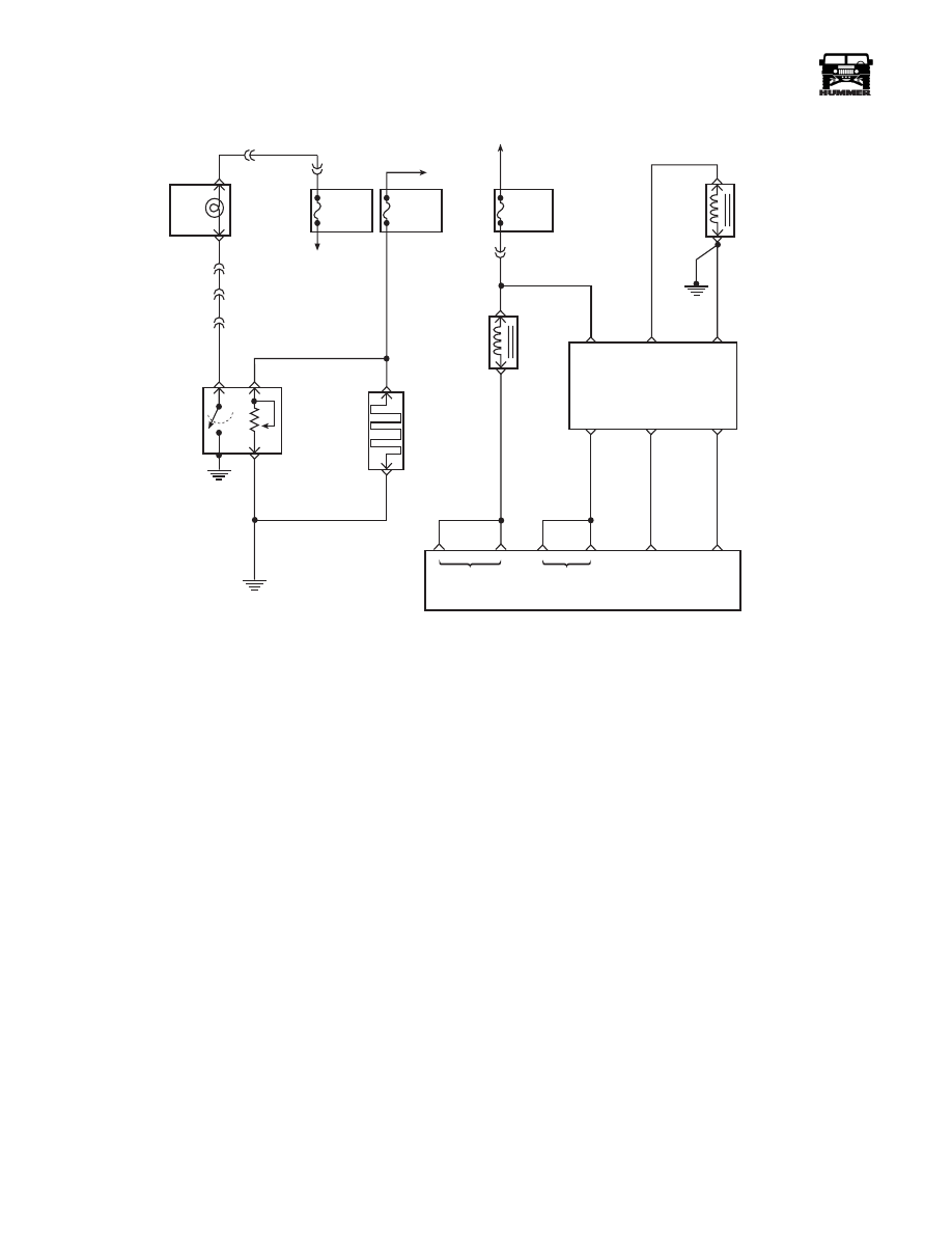
FUSE 3B
20AMP
EXTERIOR
FUSE BOX
DRAIN
FILTER
HOT IN RUN
AND START
WATER IN
FUEL LIGHT
LEFT HAND
STATUS CENTER
C9-D
C3-F4
C1-45
B
A
327 YL
C
C9-J
WATER IN
FUEL
SENSOR
FUEL
HEATER
291 PK
57 BK
G2
57 BK
C
A
9-S12-056
FUSE 4B
5AMP
INTERIOR
FUSE BOX
TO
IGNITION
SWITCH
C3-N7
30 GY
FUSE 3A
20AMP
EXTERIOR
FUSE BOX
HOT IN RUN
AND START
C5-A4
239 PK
ENGINE
SHUTOFF
SOLENOID
FUEL
SOLENOID
701 DB
A
A
A
B
C
D
F
E
A
B
FUEL
SOLENOID
DRIVER
IGN
FUEL
SOLENOID
HIGH
FUEL
SOLENOID
LOW
FUEL
SOLENOID
CONTROL
CLOSURE
SIGNAL
CLOSURE
GROUND
ESO
SOLENOID
CONTROL
FUEL INJECT
CONTROL
CLOSURE
SIGNAL
CLOSURE
GROUND
712 LG
713 RD
491 BK
POWER
CONTROL
MODULE
C28-C15
C28-D3
C28-C3
C27-C13
C29-A1
Нет комментариевНе стесняйтесь поделиться с нами вашим ценным мнением.
Текст