Hummer H1 (2002+). Manual — part 276
_____________________________________________________
PCM/Tech 1 Scan Tool 37
®
05745159
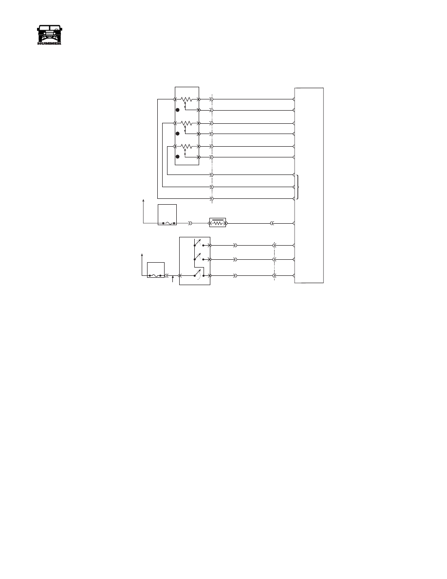
DTC P0123 Accelerator Pedal Position (APP)
Sensor 1 Circuit High Voltage
Circuit Description
The Accelerator Pedal Position (APP) module provides a volt-
age signal that changes relative to accelerator position. There
are three sensors located within the APP module that are scaled
differently. This is a type C DTC.
Conditions for Setting the DTC
• Voltage is greater than 4.75 volts on APP 1 sensor.
• Conditions met for 2 seconds.
Action Taken When the DTC Sets
• The input from APP 1 sensor is ignored.
• A current and history DTC will set but it will not turn on
the “Check Throttle” lamp. The throttle will operate
normally as long as there is only one sensor malfunc-
tioning. If two different APP sensors have a malfunc-
tion, the “Check Throttle” lamp will light and the PCM
will limit power. If three APP sensors have a malfunc-
tion present, the “Service Throttle Soon” lamp will light
and the PCM will only allow the engine to operate at
idle.
Conditions for Clearing the MIL/DTC
• A History DTC will clear when forty consecutive
warm-up cycles that the diagnostic does not fail (coolant
temperature has risen 5°C (40°F) from start up coolant
temperature and engine coolant temperature exceeds
71°C (160°F) that same ignition cycle).
• Use of a Scan Tool
Diagnostic Aids
A scan tool reads APP 1 position in volts. It should read about
.45 to .95 volt with throttle closed and ignition “ON” or at idle.
Voltage should increase at a steady rate as throttle is moved to-
ward Wide Open Throttle (WOT). Also, 90% pedal travel is
acceptable for correct APP operation. Scan APP 1 sensor while
depressing accelerator pedal with engine stopped and ignition
“ON”. Display should vary from about .74 volt when throttle is
closed to about 3.7 volts when throttle is held at Wide Open
Throttle (WOT) position. A P0123 will result if the ground cir-
cuit is open or the signal circuit is shorted to voltage. Refer to
Intermittents in Section 2.
Test Description
Number(s) below refer to the number(s) on the diagnostic ta-
ble.
2. This step determines if DTC P0123 is the result of a hard
failure or an intermittent condition.
3. This step checks the PCM and wiring.
FUSE 5C
10AMP
INTERIOR
FUSE 3A
10 AMP
EXTERIOR
ON/
OFF
SET
COAST
RESUME
ACCEL
HOT IN RUN
AND START
HOT IN RUN
AND START
A
29
42
37
C1
C29-A11
C29-B11
C27-D10
C28-D14
C28-C2
C27-D12
C27-D3
C27-D4
C27-D6
C29-B2
C29-B1
C27-C5
C29-A12
C5-D3
C5-A4
A
B
154 TN
151 GY
152 DB
153 LG
ON / OFF
SIGNAL
SET
COAST
SIGNAL
RESUME
ACCEL
SIGNAL
WASTEGATE
SOLENOID
CONTROL
5 VOLT
REFERENCE
APP 3
SIGNAL
GROUND
APP 1
SIGNAL
GROUND
GROUND
D
B
C
A
G
E
F
J
K
3
1
2
C1
22
20
14
15
60
32
53
17
44
720 TN
717 WH
723 YL
724 DG
725 GY
718 DB
719 BR
721 LB
722 PP
ACCELERATIOR
PEDAL POSITION
SENSOR
POWERTRAIN
CONTROL
MODULE
(PCM)
APP 2
SIGNAL
9-S12-055
B
C
D
295 BR
YL
GRN
RD

38
PCM/Tech 1 Scan Tool
_____________________________________________________
®
DTC P0123 - Accelerator Pedal Position (APP) Sensor 1 Circuit High Voltage
Step
Action
Value(s)
Yes
No
1
Important:
Before clearing DTC(s) use the scan tool “Capture Info” to
record Freeze Frame and Failure Record for reference, as data will be lost
when “Clear Info” function is used.
Was the
“On-Board Diagnostic (OBD) System Check”
performed?
—
Go to Step 2. Go to
OBD Sys-
tem Check.
2
1. Ignition “ON”, engine “OFF”.
2. With the throttle closed, observe APP 1 display on the scan tool.
Is APP 1 above the specified value?
4.75v
Go to Step 4. Go to Step 3.
3
DTC is intermittent. If no additional DTCs are stored, refer to “Diagnostic
Aids”. If additional DTCs were stored, refer to those chart(s).
—
Go to the
applicable
DTC table.
Go to
Diagnostic
Aids.
4
1. Disconnect the APP sensor electrical connector.
2. Observe the APP 1 display on the Scan Tool.
Is APP 1 less than the specified value?
.25v
Go to Step 5. Go to Step 6.
5
Probe APP 1 sensor ground circuit at the APP sensor harness connector
with a test light connected to B+.
Is the test light “ON”?
—
Go to Step 7.
Go to Step 8.
6
1. Check for a short to voltage on the APP 1 sensor signal circuit.
2. If the APP 1 sensor signal circuit is shorted, repair it as necessary.
Was the APP 1 sensor signal circuit shorted?
—
Go to Step 11. Go to Step 10.
7
Check for poor electrical connections at the APP sensor and replace termi-
nals if necessary.
Did any terminals require replacement?
—
Go to Step 11.
Go to Step 9.
8
1. Check for an open sensor ground circuit.
2. If a problem is found, repair as necessary.
Was APP 1 sensor ground circuit open?
—
Go to Step 11. Go to Step 10.
9
Replace the APP module.
Is Action complete?
—
Go to Step 11.
—
10
Replace the faulty PCM.
Notice:
If the PCM is faulty, the new PCM must
be programmed. Go to
PCM replacement and programming procedures.
Is the action complete?
—
Go to Step 11.
—
11
1. Using the Scan Tool, select “DTC”, “Clear Info”.
2. Start engine and idle at normal operating temperature.
3. Select “DTC”, “Specific”, then enter the DTC number which was set.
4. Operate vehicle within the conditions for setting this DTC as specified in
the supporting text.
Does the Scan Tool indicate that this diagnostic Ran and Passed?
—
Go to Step 12.
Go to Step 2.
12
Using the Scan Tool, select “Capture Info”, “Review Info”.
Are any DTCs displayed that have not been diagnosed?
—
Go to the
applicable
DTC table
System OK

___________________________________________________
PCM/Tech 1 Scan Tool 38.1
®
05745159
DTC P0126 Engine Coolant Temperature (ECT) Insufficient for Stable Operation
Circuit Description
While the engine is warming, the PCM monitors the ECT sen-
sor to determine how long it takes the engine to reach the cool-
ant temperature required for “Closed Loop” operation. DTC
P0126 will set if the PCM determines that the engine does not
reach “Closed Loop” temperature in a specified amount of
time. This test will not run if either the intake air or engine
coolant temperature is too low at start up. The PCM will only
run this DTC on a cold start and only once per cold start.
Conditions for Running the DTC
• The PCM performs this DTC diagnostic once per igni-
tion cycle until a pass or fail condition exists.
• The engine operation time is greater than 600 seconds
• The DTCs P0112, P0113, P0117 and P0118 are not set.
• The engine coolant is less than 56˚C (133˚F).
• The intake air temperature is greater than -7˚C (20˚F)
or
• The engine operation time is greater than 300 seconds
• The DTCs P0112, P0113, P0117, and P0118 are not set.
• The engine coolant temperature is less than 56˚(133F).
• The intake air temperature is greater than -7˚C (22˚F).
Conditions for Setting the DTC
• The fuel burned since start up is greater than 1,000,000 cu. mm.
• The total idle time since start up is less than 450 seconds.
• The fuel burned since start up is greater than 468,120 cu.mm.
• The total idle time since start up is less than 225 seconds.
Action Taken When the DTC Sets
• The PCM illuminates the Malfunction Indicator Lamp
(MIL) on the second consecutive drive trip that the diag-
nostic runs and fails.
• The PCM records the operating conditions at the time
the diagnostic fails. The first time the diagnostic fails,
the “Failure Records” will store this information. If the
diagnostic reports a failure on the second consecutive
drive trip, the “Freeze Frame” records the operating
conditions at the time of failure and updates the “Failure
Records”.
Conditions for clearing the MIL/DTC
• The PCM will turn the MIL off after three consecutive
drive trips that the diagnostic runs and does not fail.
• A last test failed (Current DTC) will clear when the ig-
nition is cycled and the diagnostic runs and does not fail.
5 VOLT
REFERNCE
CKP
SENSOR
SIGNAL
SENSOR
GROUND
CRANK
SHAFT
POSITION
SENSOR
(CKP)
A
B
B
A
B
B
A
A
C
C
C5
BOOST/
BARO
PRESSURE
SENSOR
INTAKE AIR
TEMPERATURE
SENSOR (IAT)
ENGINE
COOLANT
TEMP
SENSOR
(ECT)
POWERTRAIN
CONTROL
MODULE
CKP
SENSOR
SIGNAL
SENSOR
GROUND
5 VOLT
REFERENCE
BOOST
SENSOR
SIGNAL
SENSOR
GROUND
IAT
SENSOR
SIGNAL
ECT
SENSOR
SIGNAL
C29-A5
651 BK
C29-B12
C27-D13
C27-C14
C27-C1
349 YL
359 BK
350 GY
394 LG
651 PP
354 YL
357 TN
9-S12-066
B9
B11
B12
B10
B5
C4
C5
C27-C11
C27-C4
359 PP
651 BK
3-1-01

38.2
PCM/Tech 1 Scan Tool
___________________________________________________
®
• A history DTC will clear after forty consecutive warm
up cycles, if no failures are reported by this and any
other emission related diagnostic.
• PCM battery voltage is interrupted.
• Using a scan tool.
Diagnostic Aids
• Using “Freeze Frame” and/or “Failure Records” data
may aid in locating an intermittent condition. If the DTC
cannot be duplicated, the information included in the
“Freeze Frame” and/or “Failure Records” data can be
useful in determining how many miles since the DTC
set. The Fail Counter and Pass Counter can also be used
to determine how many ignition cycles the diagnostic
reported a pass and/or a fail. Operate the vehicle within
the same freeze frame conditions (RPM, load, vehicle
speed, temperature etc.). that were noted. This will iso-
late when the DTC failed.
• If other DTCs are set that share the same ground and/or
5.0 volt reference circuit, check for faulty connections
and for faulty wiring.
• If the engine has been allowed to sit overnight, the en-
gine coolant temperature and intake air temperature val-
ues should display within a few degrees of each other.
• If the engine coolant temperature exceeds 60˚C (140˚F),
this indicates that the engine is capable of reaching the
proper temperature, but not necessarily in the correct
amount of time. This diagnostic table must be repeated
on a cold engine, engine coolant and intake air tempera-
ture less than 50˚C (122˚F) and within 3˚C (5˚F) of each
other. The time required to reach the temperature thresh-
old must be measured. When starting a cold engine,
measure the amount of time it takes the engine to reach
the specified temperature. The engine should reach the
specified temperature within 8 minutes. If the specified
temperature is not reached within 7 minutes, check the
following:
Coolant level.
Thermostat operation.
Cooling fan.
Temperature VS Resistance.
˚C
˚F
OHMS
100
212
177
90
194
241
80
176
332
70
158
467
60
140
667
50
122
973
45
113
1188
40
104
1459
35
95
1802
30
86
2238
25
77
2796
20
68
3520
15
59
4450
10
50
5670
5
41
7280
0
32
9420
-5
23
12300
-10
14
16180
-15
5
21450
-20
-4
28680
-30
-22
52700
-40
-40
100700
Values are Approximate
3-1-01
Нет комментариевНе стесняйтесь поделиться с нами вашим ценным мнением.
Текст