Hummer H1 (2002+). Manual — part 277

___________________________________________________
PCM/Tech 1 Scan Tool 38.3
®
05745159
Test Description
Number(s) below refer to step numbers on the diagnostic table.
2. An ECT failure could cause a DTC P0126 to set, so
correct any ECT DTC that are set.
6. If it is obvious that the engine is not reaching full
operating temperature, for example the radiator
hoses never get vary warm, or there is a complaint
of little or no heat from the heater, this step could
be skipped.
DTC
P
0126 Engine Coolant Temperature (ECT) Insufficient for Stable Operation
Step
Action
Value(s)
Yes
No
1
Important:
Before clearing any DTCs, use the scan tool
option “Capture Info” to save freeze frame and failure
records for reference, as the scan tool loses data when
using the “Clear Info” function.
–––
Go to step 2.
Go to A Powertrain On
Board Diagnostic
(OBD) Systems Check
2
Are any engine coolant temperature DTCs set?
–––
Go to the applicable
DTC table.
Go to step 3.
3
a.
Connect the scan tool.
b.
Turn the ignition to the “RUN” position leaving
the engine off.
c.
Disconnect the ECT sensor.
Does the scan tool indicate the ECT sensor is at a tempera-
ture colder than the specified value?
-35˚C (-31˚F)
Go to step 4
Go to the diagnostic
chart for P0117 Engine
Coolant Temperature
(ECT) Sensor Circuit
Low Voltage.
4
Using a jumper wire, jumper the terminals at the ECT sen-
sor harness connector together.
Does the scan tool indicate the ECT sensor is at a tempera-
ture colder than the specified value?
150˚C (302˚F)
Go to step 5
Go to the diagnostic
chart for DTC P0117
Engine Coolant Tem-
perature (ECT) sensor
Circuit Low Voltage.
5
a.
Reconnect the ECT sensor.
b.
Start and idle the engine.
c.
With the engine idling, observe the ECT sensor
display on the “Engine 1 Data List” option on the
scan tool.
Important:
Allow time for the engine to warm up if it has
not already reached the specified temperature. 7 minutes is
the maximum amount of time it should take to reach this
temperature from a cold start. Less time should be neces-
sary if the engine is already warm.
Does the scan tool indicate the engine coolant temperature
has reached the specified value?
60˚C (140˚F)
System must be
rechecked on a cold
start. Refer to Diag-
nostic Aids.
Go to step 6.
6
Using a Digital Multi Meter measure the resistance of the
DCT sensor. Refer to Temperature vs. Resistance.
Is the ECT resistance close to the value indicated in the
Temperature vs. Resistance Table
___
Go to step 7.
Go to step 8.
7
For an engine cooling system problem, check for the fol-
lowing conditions:
• Thermostat operation
• Coolant level
• Coolant to water ratio
• Cooling fan operation etc.
Refer to
Engine Cooling.
Is the action complete?
___
Go to step 9.
___
8
Replace the ECT sensor. Refer to
ECT Sensor Replace-
ment.
Is the action Complete?
___
Go to step 9.
___
3-1-01

38.4
PCM/Tech 1 Scan Tool
___________________________________________________
®
9
a.
Using the Scan tool, clear the DTCs.
b.
Start the engine and idle at normal operating tem-
perature.
c.
Select “DTC Specifications”, then enter the num-
ber which was set.
d.
Operate the vehicle, within the conditions for set-
ting this DTC, until the scan tool indicates the di-
agnostic has run.
Does the scan tool indicate the diagnostics passed?
___
Go to step 10.
Go to step 2.
10
Does the scan tool display any additional undiagnosed
DTCs?
___
Go to the applicable
DTC table.
System is OK.
DTC
P
0126 Engine Coolant Temperature (ECT) Insufficient for Stable Operation
Step
Action
Value(s)
Yes
No
3-1-01
_____________________________________________________
PCM/Tech 1 Scan Tool 39
®
05745159
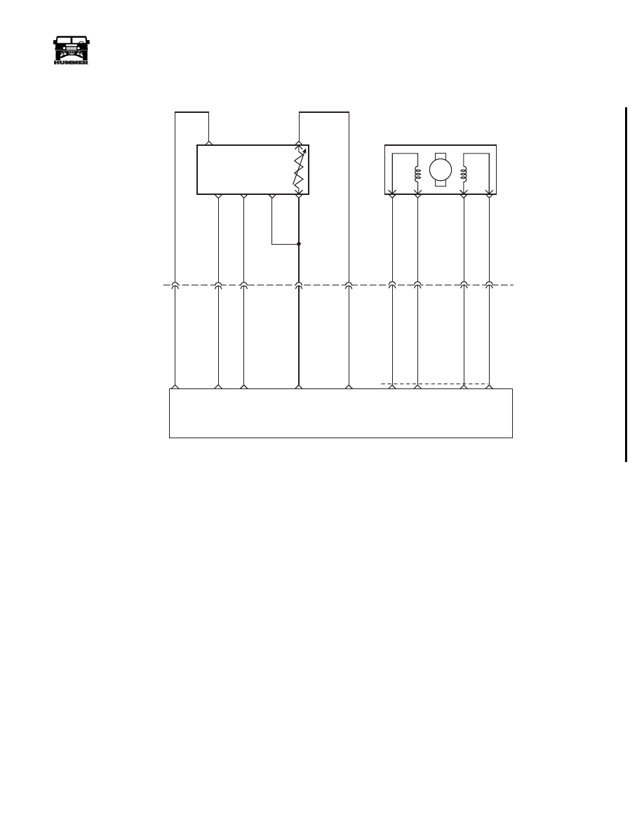
DTC P0182 Fuel Temperature Sensor Circuit
Low Voltage
Circuit Description
The fuel temperature sensor is a thermistor that controls signal
voltage to the PCM. When the fuel is cold, the sensor resis-
tance is high, therefore the PCM will see high signal voltage.
As fuel warms, sensor resistance becomes less and voltage
drops. The fuel temperature sensor is integrated with the opti-
cal sensor. This is a type B DTC.
Conditions for Setting the DTC
• Fuel temperature greater than 102°C (215°F).
• Conditions met for 2 seconds.
Action Taken When the DTC Sets
Poor idle quality during hot conditions.
Conditions for Clearing the MIL/DTC
• The PCM will turn the MIL off after three consecutive
trips without a fault condition.
• A History DTC will clear when forty consecutive
warm-up cycles that the diagnostic does not fail (coolant
temperature has risen 5°C (40°F) from start up coolant
temperature and engine coolant temperature exceeds
71°C (160°F) that same ignition cycle).
• Use of a Scan Tool.
Diagnostic Aids
A scan tool reads fuel temperature in degrees centigrade. After
engine is started, the fuel temperature should rise steadily.
Test Description
Number(s) below refer to the number(s) on the diagnostic table.
1. This step determines if DTC P0182 is a hard failure or an in-
termittent condition.
3. This step will determine if signal circuit is shorted to
ground.
A
E
B
F
D
C
5 VOLT
REFERENCE
OPTICAL/ FUEL
TEMP SENSOR
PUMP CAM
SENSOR
SIGNAL
HIGH
RESOLUTION
SIGNAL
SENSOR
GROUND
M
D
A
B
C
C5
C3
B8
C1
C12
C2
375 GY
442 BR
703 OR
156 PK
225 YL
C27-D14
C29-A4
C29-A2
C27-D9
C27-C8
FUEL TEMP
SIGNAL
SENSOR
GROUND
HIGH
RES
SIGNAL
CAM
SENSOR
SIGNAL
5 VOLT
REFERENCE
INJECTION TIMING
STEPPEN MOTOR (ITS)
A3
A2
A6
A7
709 RD
708 TN
710 OR
71
1 YL
C29
A8
A9
A10
A7
ITS
HI
ITS
LO
ITS
LO
ITS
HI
POWERTRAIN
CONTROL
MODULE
9-S12-070
Powertrain
Control
Module
(PCM)
3-1-01

44
PCM/Tech 1 Scan Tool
_____________________________________________________
®
DTC P0215 - Engine Shutoff Solenoid Circuit Malfunction
Step
Action
Value(s)
Yes
No
1
Important:
Before clearing DTC(s) use the scan tool “Capture Info” to
record Freeze Frame and Failure Record for reference, as data will be lost
when “Clear Info” function is used.
Was the “On-Board Diagnostic (OBD) System Check” performed?
—
Go to Step 2.
Go to OBD
System Check.
2
1. Ignition “ON”, engine “OFF”.
2. Using scan tool, command ESO “ON” and “OFF”.
Does ESO respond to scan tool commands?
—
Go to Step 4. Go to Step 3.
3
1. Ignition “OFF”.
2. Disconnect the PCM electrical connector.
3. Ignition “ON”, engine “OFF”.
4. With a test light connected to chassis ground, probe ESO control circuit
at PCM harness connector.
Is test light “ON”.
—
Go to Step 5.
Go to Step 6.
4
DTC is intermittent. If no additional DTCs are stored, refer to “Diagnostic
Aids”. If additional DTCs are stored refer those table(s).
—
—
—
5
Check the ESO control circuit for a poor connection at the PCM and replace
terminal if necessary.
Did the terminal require replacement?
—
Go to Step 8.
Go to Step 7.
6
1. Check the ESO control circuit for:
• an open
• faulty bulb
• faulty fuse
2. If the ESO control circuit was faulty, repair it as necessary.
Was repair performed?
—
Go to Step 8.
—
7
Replace the faulty PCM. Notice: If the PCM is faulty, the new PCM must
be programmed. Go to PCM replacement and programming procedures.
Is the action complete?
—
Go to Step 8.
—
8
1. Using the Scan Tool, select “DTC”, “Clear Info”.
2. Start engine and idle at normal operating temperature.
3. Select “DTC”, “Specific”, then enter the DTC number which was set.
4. Operate vehicle within the conditions for setting this DTC as specified in
the supporting text.
Does the Scan Tool indicate that this diagnostic Ran and Passed?
—
Go to Step 10.
Go to Step 2.
9
Using the Scan Tool, select “Capture Info”, “Review Info”.
Are any DTCs displayed that have not been diagnosed?
—
Go to the
applicable
DTC table
Go to Step 2.
Нет комментариевНе стесняйтесь поделиться с нами вашим ценным мнением.
Текст