Hummer H1 (2002+). Manual — part 167

_____________________________________________________________________
Body 10-39
®
05745159
Figure 10-66: Door Hinges
Adjustment
1.
Loosen twelve-point screws securing upper and lower
door hinges to pillar (Figure 10-66).
2.
Raise door as high as possible. Push hinges toward front of
vehicle as far as they will go, and tighten twelve-point
screws 6 lb-ft (8 N•m).
3.
Loosen twelve-point screws securing upper and lower
hinge plates to door.
4.
Close door and tighten twelve-point screws.
Manual Window Regulator (Optional)
NOTE:
At this point it is assumed that door panel has been re-
moved for access to window regulator.
Removal
1.
Remove nuts and lockwashers securing regulator post to
window assembly (Figure 10-67).
2.
Remove screws and lockwashers securing regulator post
to door.
3.
Remove screws, lockwashers and regulator from door.
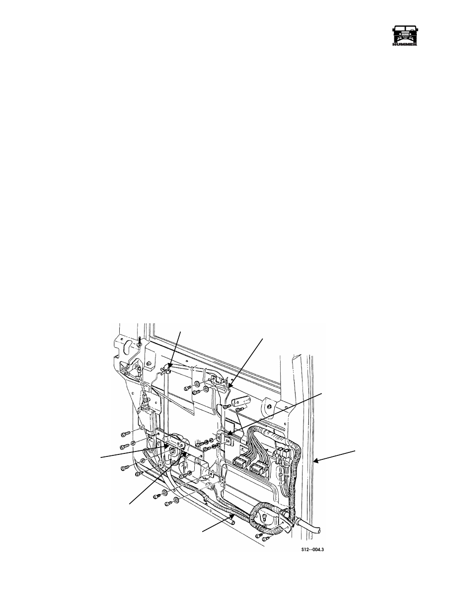
Figure 10-67: Window Regulator Mounting
Installation
1.
Secure regulator to door with lockwashers and screws.
2.
Secure regulator post to door with lockwashers and
screws.
3.
Secure regulator post to window assembly with
lockwashers and nuts.
UPPER
HINGE
PLATE
LOWER
HINGE
PLATE
LOWER
DOOR
HINGE
PILLAR
UPPER
HINGE
DOOR
DOOR
DOOR
WINDOW
REGULATOR
REGULATOR
ASSEMBLY
POST
10-40
Body
______________________________________________________________________
®
POWER WINDOWS
Power Window Regulator Replacement
Removal
NOTE:
Operate motor to position glass in opening to provide
access to two screws securing glass and its bracket to regulator.
If motor is inoperative, other means to remove these screws
will be necessary such as drilling access holes in door inner
panel.
1.
Remove power window and door lock switches from door.
Disconnect switches from power window and door lock
harness connectors.
2.
Remove door trim and vapor barrier .
CAUTION: Support window in full up position during regula-
tor removal to avoid damage.
NOTE:
Prior to removal, mark location of screws for installa-
tion.
3.
Disconnect power window and door lock harness
connector from regulator motor (Figure 10-68) (push
locking tab up on bottom of connector).
4.
Remove two screws and lockwashers securing regulator
bracket to door. Discard lockwashers.
5.
Remove screw, lockwasher, and regulator bracket from
regulator. Discard lockwashers.
6.
Remove screw securing regulator motor to door.
7.
Remove four screws and lockwashers cable and bracket
assembly to door. Discard lockwashers.
8.
Remove two screws, lockwashers, and washers securing
regulator cable and bracket assembly to window bracket.
Discard lockwashers.
9.
Remove tie strap and regulator from door. Discard tie
strap.
Installation
1.
Install regulator in door and secure with tie strap
(Figure 10-68).
2.
Secure regulator cable and bracket assembly to window
bracket with two washers, lockwashers, and screws.
3.
Secure regulator cable and bracket assembly to door with
four lockwashers and screws.
4.
Secure regulator motor to door with screw.
5.
Install regulator bracket on door with two lockwashers and
screws.
6.
Secure regulator bracket to regulator with lockwasher and
screw.
7.
Connect power window and door lock harness connector
to regulator motor.
8.
Check operation of regulator.
9.
Install door trim and vapor barrier.
10. Install power window and door switches on door. Connect
power window and door lock harness connectors to
switches.
Figure 10-68: Power Window Regulator
TIE STRAP
REGULATOR CABLE AND
BRACKET ASSEMBLY
WINDOW BRACKET
DOOR
POWER WINDOW
AND DOOR LOCK
HARNESS
REGULATOR
BRACKET
REGULATOR
MOTOR

_____________________________________________________________________
Body 10-41
®
05745159
DOOR SEALS REPLACEMENT
NOTE:
The door seals come in bulk and must be cut to the ap-
propriate lengths. For hard top vehicles, cut 12 feet for the
doors and 10 feet for the body opening. For soft-top vehicles,
cut 6 feet for the doors and 5 feet for the body opening.
Removal
NOTE:
Note position of old seals before removal.
1.
Remove door strap so that door will swing open far
enough to access seals.
2.
Remove the old seal from the door frame and the body
area. Clean any remaining adhesive residue from the door
surface.
Installation
1.
Cut the door and body seals to the proper lengths (see note
above).
2.
Beginning at the bottom of the door, press door seal
around the outside of the door frame (Figure 10-69).
Figure 10-69: Door and Body Seal Replacement
3.
Apply body seal in the same location as the seal that was
removed.
4.
Install door strap.
Figure 10-70: Body Seals Location
DOOR STOP STRAP ASSEMBLY REPLACEMENT
Removal
1.
Remove bolt, washer, and door stop strap assembly from
door (Figure 10-71).
2.
Remove two bolts, washers, door stop strap assembly, and
courtesy light from A-pillar (front door only).
3.
Remove bolt, washer, and door stop strap assembly from
B-pillar (rear door only).
Installation
1.
Secure door stop strap assembly to door with washer and
bolt. Tighten bolt 12 lb-ft (16 N•m) (Figure 10-71).
2.
Secure courtesy light and door stop strap assembly to A-
pillar with two washers and bolts. Tighten bolts to 12 lb-ft
(16 N•m) (front door only).
3.
Secure door stop strap assembly to B-pillar with two
washers and bolts. Tighten bolts to 78 lb-ft (106 N•m)
(rear door only).
DOOR GLASS
Door Glass Replacement
NOTE:
Door glass replacement is the same for all doors. This
procedure covers the right front door.
Removal
1.
Remove window regulator.
2.
Remove beltline seal (Figure 10-72).
NOTE:
Mark location of screws prior to removal for installa-
tion.
3.
Remove four screws, lockwashers, front and rear chan-
nels, and door window seals from door.
4.
Rotate glass/lift channel bracket assembly 90 degrees and
remove through window opening (Figure 10-73).
DOOR STRAP
BODY SEAL
CROSS SECTION
DOOR SEAL
CROSS
SECTION
DOOR
SEAL
ENDS OF
DOOR SEAL HERE
BODY SEAL
TERMINATES
HERE
BODY SEAL
TERMINATES
HERE
BODY SEALS
LOCATION
BODY SEALS
LOCATION
10-42
Body
______________________________________________________________________
®
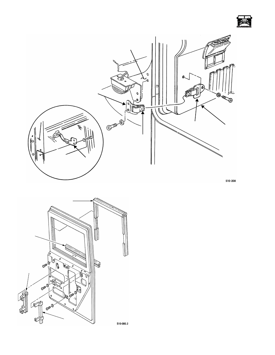
Figure 10-71: Door Stop Strap Assembly
Figure 10-72: Window Channel Locations
Cleaning and Inspection
NOTE:
Clean all components, examine for wear or damage,
and replace if necessary.
Remove all glass remains from channels and bottom of door
(Figures 10-72 and 10-73).
Installation
1.
Insert glass/lower channel bracket assembly into door
through window opening at 90° from installed position.
2.
Rotate glass/lower channel bracket assembly so that it is
aligned with the appropriate channels (Figure 10-73)
3.
Install glass in front and rear channels and channel
brackets, and secure channels and channel brackets to door
with four lockwashers and screws (Figure 10-72).
4.
Install upper and lower window channels.
5.
Install window regulator.
6.
Operate window several times to ensure glass is properly
aligned.
A-PILLAR
DOOR STOP
BRACKET
STRAP
DOOR STOP
DOOR
B-PILLAR
DOOR STOP
REAR DOOR
FRONT DOOR
BRACKET
BRACKET
DOOR WINDOW SEAL
BELTLINE
SEAL
FRONT
CHANNEL
REAR
CHANNEL
Нет комментариевНе стесняйтесь поделиться с нами вашим ценным мнением.
Текст